


A Hyperlink Junkie's Illustrated Field Guide
to the 1969 Triumph Bonneville
 Manual/Tech Bulletin
 Parts Illustration
 Special Tool
 Photo
Photo
 WWW Link
 Video
Video
 LH Thread
 Tips
Tips
 Traps
Traps
 Compatibility
See Documents Section above.

Foot-pounds or pound-feet? Either gets the message across, but technically only one is correct for fastener and engine torque.
Resources
Phone numbers are as dialed from North America.
Resources
 hermit.cc Hermit's Special Tools Lists
Resources
Ian Chadwick Triumph Motorcycle Models (with bibliography).
Resources
TriumphRat.net Classic, Vintage, and Veteran Triumph Forum
Britbike.com
The Triumph Forum
motos-anglaises.com Classic British Motorcycle Forum (French)
forum.fam-amv.ch Friends of Old Motorcycles Forum (Swiss)
Resources
hermit.cc Classic British MC Links Hundred of links for parts, services, accessories, books, clubs, history, tools, technical info, etc.
You've leaned on it, heated it and pounded it and that part STILL won't come out! Duh, it's a left-hand thread! Don't drive yourself nuts, consult this illustrated list of the five left-hand fasteners on a 1969 Triumph 650. Or look for the left-hand signs below in The Bonnie Ref.
Resources
Baconsdozen
Kevin C. Bacon's history and descriptions of Whitworth (BSW), BSF, BSC, UNC, UNF, SAE, AF, and BA. Includes Bacon's own size charts with conversions to metric and decimal inch dimensions. A must-read, top to bottom, richly informative.
JRC Engineering Whitworth and Other British Threads Graham White and Stephen Moore provide historical and technical perspectives on British threads - including a cogent explanation of BSW/BSF wrench sizes!
TriumphRat.net "Nuts n' bolts" A thread about nuts and bolts - how can you resist? Some interesting bits on plating, stainless, sizes, threads, and Stuart's run at BSW/BSF wrench sizes.
Naich.net "Ever Wonder Why Plumbers Get Paid So Much?" Everything you ever wanted to know about BSP. Maybe more.
Note that while American wrenches are measured across the flats (AF) of the bolt head, wrenches for the bolts in the British standard thread family are measured by the diameter of the bolt's threads.
Resources
TriumphRat.net Locktite discussion...
TriumphRat.net John Healy, the only four places to use Loctite on a Triumph
Where to use Loctite thread locker on a Triumph 650 is a question that will elicit different answers depending upon who is asked.
According to John Healy (see link above), there are just four places to use Loctite on a Triumph 650:
Thomas G. Gunn, Jr., in his seminal 1987 work "Overhaul Manual For 650cc Unit Construction Triumph Motorcycle Engines since 1963", suggests using Loctite in six places:
It's interesting to note that out of John Healy's four places to use Loctite and Thomas G. Gunn Jr.'s six places, the only concurrence between the two lists is the crankcase bolts.
Other disciples have suggested using Loctite on crankcase studs, although in that application it's used more as a sealant than as a thread locker. In addition, amateur Loctite enthusiasts (now who said that?) have devised many other ingenious applications as well.
The most popular Loctite thread locker products (also see chart below for typical applications):
Resources
TriumphRat.net Which Gasket sealer, there are so many
TriumphRat.net TR7RVMan on sealants, and how to know if your Hylomar is out of date
TriumphRat.net "T100R gearbox assembly sealant"
Britbike.com "
Loctite plastic gasket"
F/G Engine "
Hylomar...the 'secret weapon'" F/G's excellent run-down of Hylomar products includes Blue, M, and others and is loaded with useful info and practical tips.
The following chart, an interpretation/extrapolation of the TriumphRat.net links above, summarizes opinions about which sealant and which thread lockers to use, and where. Green dot items are commonly recommended, while yellow dots indicate that extra caution is required. Red dotted scenarios may best be avoided altogether. Rationale for the classifications should be apparent from the product descriptions that follow.

Some popular sealant products:
Hylomar M performs just like Blue, but its solvent is California approved. F/G Engine has an excellent write-up of several Hylomar products, including Blue and M. Very informative and lots of good practical tips. Read it and reap!
Resources
TriumphRat.net
"Gaskets" Don't blow a gasket, get good advice here.
Hermit.cc "Rocker Box Gaskets"
Hermit.cc "Anneal and Install Head Gasket"
Hermit.cc "Primary Chaincase Cover and Gasket"
| Characteristics / Product | Loctite 641 | Loctite 660 | Loctite 620 |
| Applications | Press fitting, repairing, retaining | High temp slip fitted parts, retaining | |
| Color | Yellow | Silver | Green |
| Cure Type | Anaerobic cure | Anaerobic cure | |
| Fixture Time | 20 min. | 15 min. | 60 min. |
| Gap Fill | 0.15 mm | 0.25 - 0.5 mm | 0.15 - 0.25 mm |
| Strength | Medium strength | High strength, gap filling, thixotropic | Medium to high strength, gap filling, high temperature, high viscosity |
| Operating Temp | 55 - 150C (-65 - 300°F ) | -65 - 300°F (-55 - 150°C ) | -55 - 230C (-65 - 450°F ) |
| Format | Paste | Liquid | |
| Substrates | Metal: Steel | Metal: Steel | Metal: Steel |
| Removal | Requires heat |
Resources
TriumphRat.net Recommended Assembly Lube
Assembly lube products are designed to provide lubrification to moving engine parts during initial start-up. An important advantage of assembly lube over motor oil is that while oil will drain away from parts relatively quickly, assembly lube coats parts and remains in place pretty much indefinitely, thus eliminating the need to compress the time between assembly and initial engine start-up.
In the TriumphRat.net thread above, Peg suggests using assembly lube for big ends, piston skirt (very sparingly), cam lobes and bushes, tappet blocks, rocker arms, and valve stems.
Resources
BritBike.com
"Heating Engine Cases & Other Parts"
Oven, barbecue, hot tub - your choice.
Resources
Workshop Manual (1969 650cc Twins) Section A: Lubrication Table of Contents
Workshop Manual (1969 650cc Twins) Section A1: Routine Maintenance
Workshop Manual (1969 650cc Twins) Section A2: Recommended Lubricants
Oil products have changed a great deal since the '60s. The WS Manual lubricant recommendations are outdated and obsolete. For modern oil recommendations see individual sections below.
Resources
Workshop Manual (1969 650cc Twins) Section A3: Engine Lubrication
Hermit.cc Percentage of Zinc Content for Popular Oils
TriumphRat.net Comments & recommendations (UK & US) on crankcase oil/ZDDP (zinc) and gearbox oil/yellow metals
BritBike.com
Very informative synthetic oil thread
540ratblog "Motor Oil Engineering Test Data"
Britbike.com "Crankcase vent tube discharge question" TR7RVMan elucidates upon Triumph crankcase venting
Hemmings.com "Tech 101: Zinc in oil and its effects on older engines"
According to an article ("Tech 101: Zinc in oil and its effects on older engines"), modern oil manufacturers have reduced the amount of 'zinc' (actually ZDDP [zinc dialkyldithiophosphate] or ZDTP [zinc di-thiophosphate]) in their products for various reasons, including prolongation of the life of catalytic converters. When used in older (classic) car and motorcycle engines, the low-zinc products fail to provide sufficient protection against start-up engine wear.
Here's a list that gives zinc content of a few oils on the market, In relatively cool climates, Shell Rotella 15w-40 seems to work quite well.
Resources
Workshop Manual (1969 650cc Twins) Section A4: Changing the Engine Oil & Cleaning the Filters
Triumph specified an engine oil change interval of 1,500 miles. Of course the only oil filtering back in the day was the wire screens in the oil tank and the crankcase.
Even after I installed an external oil filter (see "Using an Oil Filter" just below), I continued changing engine oil (and filter) at 1,000 mile intervals. And to simplify things I change crankcase oil and primary chaincase oil at the same time. So far, oil changes are cheaper than engine rebuilds!
Capacity
Drain bolts
Some point out the difficulty in cleaning thoroughly around the crankcase oil drain plug due to its proximity to the crankcase joint and the angle at which they meet. They suggest that removing the crankcase drain bolt is a bad idea because of the attendant risk of contaminating engine oil with dirt.
Since only a small amount of oil (less than a quarter of a cup) drains out of the crankcase anyway, I adopted the practice of removing the drain plug once a year during winter maintenance to inspect and clean the filter screen. The same goes for the filter screen in the oil tank.
Resources
Glenn "Phrog" Davidson's Norton filter head mounting bracket design
Colorado Norton Works Oil Filter Adaptor for Norton Filter Head
Probably the single most important modification one can make to a classic British bike is to install a modern external oil filter. It has been said that doing so can quadruple the life of an engine. That estimation may be slightly exaggerated, but there's no doubt about the extra protection afforded to an engine by an add-on oil filter
The most common retro-fit oil filter system utilizes a Norton-type oil filter head, connected in the return oil line between the oil pump and the oil tank, as diagrammed below.
The go-to mounting bracket design is that of Glenn Davidson (see link above). The oil filter head and Davidson-style mounting bracket are commonly mounted at the bottom of the down tube, facing the rear of the bike at a height which gives just enough clearance between the filter and the center stand in both it's up and down positions. It may be necessary to grind just a bit off the "lump" at the bottom of the downtube.
Note that the Triumph oil tank connections and oil pipe junction block pipes are 1/4", while those of the Norton filter head are 3/8". The compromise is to use 5/16" (automatic transmission cooler) hose to make the connections between the filter head and the oil tank and oil junction block. It is a very tight fit on the filter head's 3/8" fittings, and somewhat loose on the 1/4" pipes of the oil tank and oil junction block, but once they are well-clamped the connections shouldn't leak.
Another possiblity is to replace the Norton filter head's 3/8" stubs with 1/4" ones. This mod was performed on my Bonnie's filter head recently so now I use 1/4" hose throughout.
The following filters work satisfactorily with the Norton filter head, and others can be found on cross-reference lists online.
In a TriumphRat.net post "obollox" nominates the following list:
Finally, Britbike.com forum member "JJC" posted this list of 222 filters supposedly equivalent to the Norton filter.
A simple double-threaded adaptor is available from Colorado Norton Works (see link above) which permits use of more widely available and potentially less expensive oil filters, such as the following:
Resources
Workshop Manual (1969 650cc Twins) Section A8: Removing & Replacing the Oil Pipe Junction Block
Workshop Manual (1969 650cc Twins) Section A9: Removing & Replacing the Rocker Oil Feed Pipe
Incorrect installation of oil lines will result in catastrophic damage to an engine.
The oil pipe junction block connections described here are only for Triumph unit 650s. No less an authority than Mr. Pete informs us that connections for pre-unit Triumphs are the exact opposite.
In the following descriptions of oil line connections, "front" and "forward" reference towards the front of the motorcycle, and "rear" and "back" reference towards the rear of the motorcycle.
The feed line is the rear oil line connection on the oil tank (union nut). The feed line goes to the forward connection pipe on the oil junction block. So oil tank rear to oil junction block forward. (Refer to illustration just below).
The return oil line is the front connection on the oil tank. It goes to the oil junction block's rear connection pipe. So oil tank front to oil junction block rear. (Refer to illustration just below).
Oil to the rockers was fed from the oil tank tower in 1966 - in all other years, before and after, the feed is taken from the scavange return at the bottom of the tank.
Incorrect installation of oil lines will result in catastrophic damage to an engine.
A Norton oil filter head is ordinarily installed in the return oil line as per the following diagram.
Removing the oil lines from the oil junction block tubes can be a bit difficult, especially if they have been undisturbed for a long time. The job can be made a little easier by removing the outer gearbox cover first.
In any case, it is wise to heed the WS Manual's explicit warning to avoid over-stressing the tubes.
Resources
BritBike.com "Oil spewing from crankcase vent hose" The solution to a somewhat unique problem provoked this interesting discussion of crankcase venting. Definitely worth a read.
BritBike.com "Crankcase breather check?" One of the best explains how to test the crankcase venting system's disc breather. Very educational.
BritBike.com "
Triumph Breather Disc" Shippy passes along his research on 70s and later Triumph crankcase breathing setup - highly educational!
Unit construction engines prior to 1970 relieved crankcase pressure via a breather valve installed in the end of a camshaft. The valve is simply a disk with two openings opposite each other. As the opposite openings rotate with the camshaft they provide venting of the pressure created by the motion of the parallel twins' pistons. The pressure follows a passage cast into the crankcase and out a stub on the bottom of the engine, to which a plastic tube is attached and routed out the back of the rear fender.
Beginning in 1970, the breathing disk was eliminated on 650 models and excess pressure was diverted through three holes drilled in the partition between the crankcase and the primary chaincase, as well as the drive side crankshaft main bearing into the primary chain case.
For this reason, the DS main bearing on 1970 and later engines should not be fitted with an oil seal.
So, on unit construction engines prior to 1970, a 3/8" plastic tubing (70-5375 Ref# 39 Fig.2 #7) connects the engine breather pipe stub (70-2724 Ref# 7 Fig.2 #7) just forward of the gearbox sprocket to the Tee (70-5370) near the top of the oil tank. Also connected to the tee is the oil tank vent pipe (70-6356, Ref# 16 Fig.23 #7), and the oil breather vent tube (82-7353, Ref# 18 Fig.23 #7)
The engine breather stub is in a constrained, out-of-the-way location. The best time to put the plastic tubing on it is with engine out of the frame.
If the engine's in the frame, this tip makes child's play of a #!@*& job: fasten a 1/4" or 5/16" wooden dowel about 10 inches long to the end of the tubing with masking tape and use it to push the tubing onto the stub. Work from the TS; prop up a mirror beneath the engine; shine a light up there. Warming the tubing with hot water helps make it slide right on. Putting the dowel toward the rear lets you see and lets you scrape along it with a sharp blade to remove by twisting. If a little tape gets left behind, no biggie. Photo
The oil breather vent tube passes on the left side just above the indentation in rear fender.
The first clamp is fastened on the left-hand side beneath the left nut holding the strap on top of the fender between the two upper shock mounts.
Resources
Workshop Manual (1969 650cc Twins) Section B33: Remove/Replace Oil Pump
Workshop Manual (1969 650cc Twins) Section A7: Stripping and Reassembling the Oil Pump
Triumph Overhaul Manual Assembling the Oil Pump
Britbike.com "
Oil Pump Confusion Unit 650cc SOLVED!"
Although Triumph made several changes to 650/750 oil pumps, they are all interchangeable according to John Healy.
| Year | Part No | Specs |
| 1963 - 1966 | E3878 | Scavenge 0.437"/ Feed 0.374" |
| 1967 - Early 1969 | E6928 | Scavenge enlarged to 0.487"/ Feed 0.374" |
| Late 1969 - 1979 | E9421 | Scavenge 0.487"/ Feed enlarged to 0.406" |
| 1980 and on | 71-7317 | Double check-valve pump (Scavenge& Feed unchanged: Scavenge 0.487"/ Feed 0.406") |
| Source: Britbike.com | ||
Resources
Workshop Manual (1969 650cc Twins) Section A5: Oil Pressure
Workshop Manual (1969 650cc Twins) Section A6: Stripping and Reassembling the Oil Pressure Release Valve
Triumph Overhaul Manual Assembling the Oil Pressure Relief Valve
Resources
Workshop Manual (1969 650cc Twins) Section H18: Oil Pressure Switch
The Bonneville Shop forum "A Guide for BSA and Triumph Oil Pressure Switch Identification", Dave Porter.
TriumphRat forum Oil pressure switch for '70 T120?.
TriumphRat forum Excerpt from another oil pressure switch thread.
If so desired, the oil pressure switch can be removed and replaced by a blanking plug.
When fitting either a replacement oil switch or a blanking plug, care must be taken to insure that its threads correspond correctly to those of the timing cover. Most timing covers are made for straight threads, but threads in some are tapered. Consult the links above to determine the correct part for your bike.
Caution! Fitting a straight-threaded part into a tapered-threaded cover can easily result in a cracked timing cover!
Resources
Workshop Manual (1969 650cc Twins) Section E2: Removing and Replacing the Oil Tank
Battery Carrier/Oil Tank Mounting (2 photos)
TriumphRat.net A thread with some interesting info on oil tanks, oil pumps, and oil flow
Britbike.com A thread on repairing Triumph oil tanks
Britbike.com
Another oil tank repair thread
BritBike.com
Some ideas on cleaning oil tanks
From 1967 to 1970 the unit 650 Triumph oil tank was unchanged. However, according to RF Whatley, Triumph made several modifications to engine lubrication in 1966, including a new (and problematic) oil tank design. Whatley tells us that the modified design was limited to several months of production and most were changed under warranty. However, an oil tank with the rocker feed coming off the top instead of the bottom is of the problematic 1966 design and should be replaced with a later model.
Use Murphy's liquid soap on the rubber parts to help ease them in.
Important that tank "hangs" well to avoid rubbing and consequential wear.
One would think that the rubber mounting would incur the wear, but the wear that occurred after my very first re-assembly was to the tank's mounting peg, not the rubber.
A proper adjustment is obtained by rotating the "C" clamp mounting bracket until all parts of the tank are suspended clear of the frame.
In case you ever need to know, HenryAnthony on Britbike.com forum informs us that the measurement between the barrels holding the rubber upper mounts is 4-1/4", and the measurement between the battery holder straps they bolt up to is 4-1/2".
Resources
Workshop Manual (1969 650cc Twins) Section A21: Check Procedure for Wet Sumping
TriumphRat.net Peg explains Triumph oil pump operation and describes wet sumping and oil drain down and their causes.
Resources
Workshop Manual (1969 650cc Twins) Section A12: Primary Chaincase Lubrication
Oil change info below does not apply to engines made after late 1969. Prior to that time, crankcases and primary chaincases were completely separate from each other, and each had their own oil supply. But starting in late 1969, Triumph modified crankcase breathing by venting the crankcase into the primary chaincase, and thus the two began sharing a common oil supply.
The late 1969 changes weren't documented in parts books or manuals until 1970. Therefore, if your engine is a late 1969 that shares oil, consult 1970 documentation for parts and oil change info.
While it is a common practice to use ATF primary chain case lube in engines whose crankcases and chain cases are separate, attempting to do so on engines that share oil between engine and primary chaincase would be disastrous. Know what you got.
Change primary chaincase oil at 1,000 mile intervals. Drain and replace with 350cc of 30w non-detergent oil.
As noted just above, a fairly common practice is to replace non-detergent primary chaincase oil with ATF - but NOT on units that share oil between engine and primary.
The chaincase oil drains slowly because it needs to flow past the primary chain tension adjuster. The drip, drip, drip flow of oil even when it's hot takes hours so I usually give it all day or overnight.
Avoid damaging threads in the soft aluminum case, go easy tightening the drain bolt.
If the volume of oil drained from the primary exceeds what was put in, it is likely an indication of a failed DS crankshaft seal allowing passage of engine oil into the chaincase.
Resources
Workshop Manual (1969 650cc Twins) Section A11: Gearbox Lubrication
MachineryLubrication.com "The Effects of EP Additives on Gearboxes"
Lucas oil representative 'Don't use our products with yellow metal' (2014)
Britbike.com
"Bronze-friendly gear oil recommendation?"
TriumphRat.net Comments & recommendations (UK & US) on crankcase oil/ZDDP (zinc) and gearbox oil/yellow metals
Hermit.cc Hermit's Gearbox Oil/Yellow Metal Experiment, with conclusion.
Opinions differ about using GL5 spec gear oils around the yellow metal bushings and thrust washers used in our Triumph gearboxes.
GL5 oils have high concentrations of sulphur and sulphur reacts with yellow metals chemically to break them down. So say those who believe GL5 is harmful. Yet many others say they've used GL5 for years without problems.
Why take a chance? I was always disinclined to use GL5 gear oil in my Bonnie's gearbox.
Oil companies say GL5 products are now safe because they've reduced active sulphur, which eats yellow metals, in favor of inactive sulphur, which is less harmful while still providing the protective qualities of active sulphur.
I don't find "less harmful" all that reassuring, frankly.
However, since doing my own yellow metal and GL5 experiment I do feel a bit more comfortable about GL5. But I still prefer good old GL4.
For those who harbor doubts, the following list of oil descriptions are those which are said to be, at least potentially, harmful to yellow metals:
For other gear oil recommendations (including many in UK) see this link above in TriumphRat.
There are three hex heads on the bottom of the gearbox: the 3/4" index plunger holder (57-2172); the 7/16BS (3/8W) drain plug with level tube (57-3851); and the 5/16" gearbox level plug (21-0543).
The level plug threads into the drain plug and together they are tucked just inside the frame member on the timing side. Since they are closer to the timing side I always removed and installed them from that side. However, access from that side is awkward due to the proximity of the frame, and recently I realized that it's actually easier to access them from the drive side.
To drain the oil, remove the drain bolt using a 7/16BS (3/8W) socket and a two or three inch extension to clear the frame. Remove carefully to avoid damage to the level tube extending above the drain bolt.
When replenishing the gearbox oil I simply measure out 500ml in a graduated container and add it through the gearbox outer cover port. You can also use the level plug to gauge fullness, but it requires patience because the heavy gear oil does take some time to work it's way through the slender level tube.
Resources
BritBike.com "
How to stop oil and gear box drain plug leaks?".
Resources
Workshop Manual (1969 650cc Twins) Section A16: Front Fork Lubrication
Gavin Eisler's tip on draining fork oil:
"When changing fork oil remove RHS top nut, remove LHS drain screw, doing opposites stops oil gushing out the top as the bike settles. Read that in the manual, after doing it wrong for years, this saves a lot of mess. I like to flush the old oil with a little kerosene to get the last of the muck out."
Resources
Workshop Manual (1969 650cc Twins) Section A10: Contact Breaker Lubrication
Note that the nipple on the speedometer gearbox grease fitting is not a standard size. However, a standard grease gun will inject a sufficient amount of grease to keep the gearbox well-lubed according to Stuart.
And in another post Stuart alerts us to this grease nipple source.
Resources
Triumph Workshop Manual 1969 Unit 650 c.c. Section B: The Engine
Triumph Overhaul Manual 650cc Unit since 1963
Triumph Overhaul Manual Engine Changes Relating to Major Engine Work
Triumph Overhaul Manual Service Tools for Complete Overhaul
Fig.14 Engine Mounting Plates, Footrests
Britbike.com
"Torque wrench settings", Rod bolt stretch, tappets & cams
TriumphRat.net Advice on preparing for a complete engine tear down
TriumphRat.net Engine Rebuilding Guys in the know tell us what to look for when rebuilding an engine (must-read)
Triple Cycles, UK
"Waking the Sleeping Beast" Starting an engine after a long sleep. Note: this article was written for Triples. StuartMac cautions us to add just one pint and not two to a Twin's craankcase through the primary chaincase since its crankcases is smaller,
Hermit's index to Lowbrow's 13-part 650 Rebuild Video Series.
Resources
CycleWorld "What Is The Difference Between Normal And Abnormal Combustion In A Motorcycle Engine?" An overview.
Allen W. Cline, CONTACT! Magazine
"Engine Basics: Detonation and Pre-Ignition" Detailed explanation.
Descriptions of pre-ignition and detonation found in the article and video above can be summarized this way:
"Generally detonation witness marks are not left in the center of the piston, they tend (note:I did not say always) to show up at the edge of the piston. Light detonation can most times be tolerated by a piston, heavy detonation often collapses the piston ring lands." Peg, Triumphrat.net
"Marks in the center of the piston are more likely to be the result of Pre-Ignition, a much more sinister problem. This problem tends blows holes in your piston crown, it destroys in seconds. (Pre ignition can be brought about by the heat generated by detonation)." Peg, TriumphRat.net
Things to beware of:
Here is a chart of Triumph 650 engine temperature readings taken as the engine warmed up to operating temperature. Fairly typical for ambient temps shown.
Head temps were measured in the sparkplug well with a laser unit.

Kicking back during starting is symptomatic of engine problems and potentially hazardous to the operator. The three most likely causes of kick-back are:
When considering timing advance issues it's wise to first check the alignment of the rotor's 38 degree line with actual TDC using a TDC tool or other method.
Spin speed can be a factor, particularly in the case of electronic ignition systems.
Resources
Workshop Manual (1969 650cc Twins) Section B1: Removing and Replacing the Engine Unit
Hermit.cc Removing engine using chain hoist
Resources
Workshop Manual (1969 650cc Twins) Section B39: Inspect Crankcase Components
Triumph Overhaul Manual Separating Crankcase Assembly
Triumph Overhaul Manual Assembling the Crankcase Halves
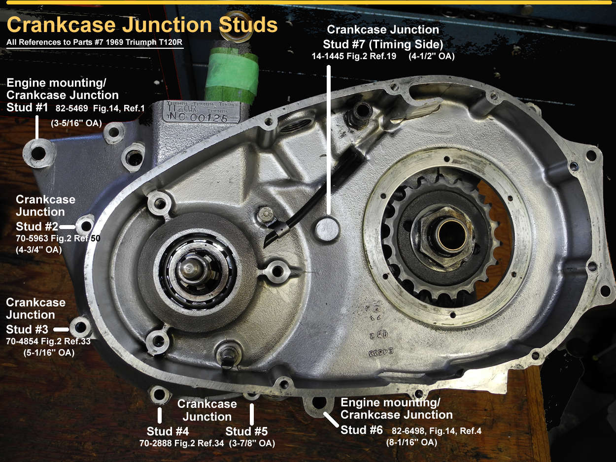
Remove studs using two locked nuts. Don't use the 12-point base nuts, instead use a couple of 14-0303 nuts (3/8-24TPI UNF) - there are 10 of them on 1969 and later 650s - can't hurt to have a couple of spares on hand. If studs resist removal, some gentle heating of the case should release them pretty easily.
The two primary side inside cylinder base studs have locating hollow dowels on them, and the threaded holes for the two timing side inside studs are through-drilled on the 650's. These should be sealed in order to prevent oil from wicking up the stud threads.
(Note that on T140 crankcases the two outer studs on the drive side are through-drilled.)

Be aware that replacement studs may not include the "pip" at one end that originals do. The pip ensures that the stud bottoms out against the bottom of the stud hole, which can't be threaded all the way to the end. If there's no pip to bottom out first, the stud's will jam against the end of the threads in the hole instead of against the bottom. This creates a stress point which can potentially create a lot of damage.
If a stud has a pip, be sure it goes into the stud hole. If a stud has no pip, consider dropping a small steel ball down the hole first so the stud bottoms out against it instead of the thread's end. Read it here, on TriumphRat.net.
On the 1969 650 engine there are eight hollow dowels
Several parts books, including #7, make a mess of the part numbers, locations, and quantities of these dowels. All the errors are described and corrected in this corrected illustration.
On his Triumph 650 Rebuild DVD, Hughie Hancox shows how to install the hollow dowels on the two crankscase cylinder pad studs with grooves for them: run them down into their crankcase grooves with a base nut. Now, why didn't I think of that?
Peg shares how to remove hollow dowels without crushing them: "I like to place a bolt in the dowel before gripping it so that it does not collapse, a little wiggle usually gets them out, they are not in very deep."
This procedure is after that shown by Hughie Hancox on his "Hughie Hancox Triumph Unit 650" rebuild DVD.
DS Crankcase Assembly
TS Crankcase Assembly
Assemble Cases Together
Resources
Workshop Manual (1969 650cc Twins) Section B36: Dismantle/Reassemble Crankshaft Assembly
Workshop Manual (1969 650cc Twins) Section B37: Stripping & Reassembling the Crankshaft Assembly
Triumph Overhaul Manual Measure crankshaft journals
Service Bulletin #67-15 "Roller Bearing (E2879) Crankshaft Drive Side on "B" Range 650cc beg.DU24875"
Service Bulletin Twin 14/72 "Metric Main Bearings"
TriumphBonneville120.co.uk "Triumph Main Bearings Used by Year and Model" Info on C2, CN, C3
BritBike.com "
Weight of a 650 crank" Very informative thread - highly recommended Triumph crankshaft reading.
YouTube Lunmad - 650 bottom end inc sludge AND easy gearbox assy All under 20 minutes.
Lowbrow Triumph 650 Disassembly & Rebuild: Part 6 The Crankshaft Begins at: 00:00.
Resources
Workshop Manual (1969 650cc Twins) Section B37: Stripping & Reassembling the Crankshaft Assembly
Triumph Overhaul Manual Installing the Sludge Trap
VintageBikeMagazine.com "Removing Triumph Sludge Tube" Text and Photos
Lowbrow "How to Remove the Triumph Sludge Trap Tube" Text and Photos
Lowbrow Triumph 650 Disassembly & Rebuild: Part 6 Sludge Trap Removal Begins at: 09:25.
The sludge trap is a metal tube fitted inside the gallery that runs through the big end connecting rod journals. Oil is forced through the timing end of the crankshaft and through oil passageways into the sludge tube. There, centrifugal force separates the particles suspended in the oil - think of a washer in spin cycle with bras and panties flattened while the water flows away. Well, maybe not such a great analogy. Anyway, inboard weep holes permit the oil to lubricate the big end bearings and then return to the crankcase sump from where it's pumped back to the reservoir.
Although it's controversial and frequently maligned, the Triumph sludge trap is actually a relatively effective oil filter. Its big drawback is that it can't be inspected or cleaned without splitting the crankcase - a major job requiring complete disassembly of the transmission and engine, although not necessary the gearbox.
Some believe that no matter how full the sludge tube becomes, oil under pressure will always make its way to the big ends.
That's a theory, but the more widely accepted notion is that a plugged sludge tube will prevent oil from flowing to the big ends with catastrophic results.
It's also widely held that after a bike sits for a long time and is then restarted, dirt particles in the tube may break off and subsequently block critical oil ways in the engine, there being more risk for machines lubricated with non-detergent oil before storage and then drained and re-filled with detergent oil before re-starting.
So without splitting the cases, how does one know whether or not the sludge tube needs cleaning/replacing? Unfortunately we can't answer this question precisely, we can only make an educated guess based on service history and engine condition.
| More Sludge Deposit | Less Sludge Deposit |
| High mileage | Low mileage |
| Using non-detergent oil | Using detergent oil |
| Running dirty oil | Frequent oil changes |
| No external oil filter (as stock) | Fitting external oil filter |
A sludge trap service interval of twenty- to forty-thousand miles seems about right for a well-maintained machine in good condition and fitted with an external oil filter. Without an oil filter (stock) one could expect a significant reduction of those figures.
On the other hand, it has been said that fitting an external oil filter quadruples the life of an engine, and it's certainly not unreasonable to expect that a sludge trap would fill more slowly under those circumstances.
Some suggest hypothetically that sludge traps on '70 and onward 650 Twins might fill up more quickly due to those models sharing oil between primary chaincase and crankcase and on the basis that the clutch produces even more sludge (think shock absorber rubbers) than the engine itself.
Sludge tubes can be quite difficult to remove as there are two hurdles: removing the cap, and removing the tube itself. Tubes don't always survive the extraction, caps rarely. However, replacement sludge tubes are not expensive. Also, caps for them are now available which have either hex heads or hex key sockets instead of the more difficult to remove slotted head on the stock item.
There are two ways to remove the tube: smack it out and pull it out. Pulling it out may contribute to higher rates of tube survival.
What size tap to use for tube removal? LowBrow video (link above) suggests 3/8"-18 N.P.T. Kevin suggests EZ-Out number 6, drill size 13/32-inch.
When replacing the sludge tube be absolutely certain that its alignment hole is actually lined up for the flywheel bolt before inserting and tightening the bolt (Grand Paul).
Resources
Triumph Overhaul Manual Assembling the Flywheel
TriumphRat.net MB walks us through Triumph
"Flywheel Evolution"
TriumphRat.net Heavy & light flywheel photos ID'd
"The T120 Crank/Flywheel amateur spotters field guide"
TriumphRat.net Balance Factors
"Dynamic ballance spec's. Does this look right"
TriumphRat.net A question of balance
"Newly balanced crankshaft
"
The three flywheel bolts are one of the four places to use Loctite on a Triumph, and the only place to use red Locktite.
Triumph made numerous modifications to the "B"-range flywheels between 1963 and 1971. As summarized below, MB listed major changes in the Triumphrat.net thread "Flywheel Evolution" (link above).
| Year | Change |
| 1963 - 1964 | Heavyweight flywheel - no timing slots |
| 1965 | Slot for TDC added |
| 1966 | Lightweight flywheel Balance factor unchanged (85%) |
| 1968 | Lightweight flywheel Slot for 38 degree max advance timing added First ones also had extra slots for timing plug re-positioned to the front of the engine, but later reverted to rear position after DU74052 |
| 1969 | Began w lightweight flywheel Reverted to heavyweight at NC.02256 - much like 1965 flywheel, but with 38 degree slot |
| 1971 | New flywheel - different profile Same balance factor and slots as 1969 flywheel Metric-sized timing side crank introduced at end of 1971 model year |
Resources
Workshop Manual (1969 650cc Twins) Section B37: Stripping & Reassembling the Crankshaft Assembly
VictoryLibrary.com "Parallel Twin Crankshaft Balancing"
CycleWorld.com "Motorcycle Engine Balancing Act", Kevin Cameron
TriumphRat.net Mr. Pete on crankshaft balance factor
Britbike.com John Healy on crankshaft balancing
TriumphRat.net Light versus Heavy Crankshafts, Balancing
The kinetic energy of the Triumph 650 parallel twin's pistons, rods, and crankshaft is essentially the same as that of a single-cylinder engine - jumpy! Therefore, in an effort to reduce vibrations for the rider's sake, at least some of the "jumpiness" is removed by "balancing" the crankshaft.
Balancing a crankshaft is a two-sided coin: balancing for fewer vibrations (greater rider comfort) inherently increases mechanical stress to the crankshaft and bearings, potentially creating abnormal wear or even out and out destruction.
On the other hand, balancing for completely minimal mechanical stress results in vibrations intolerable to riders.
So balancing to begin with is a compromise. The compromise is governed by something called the "balance factor". In simple terms, the balance factor is a chosen percentage of the reciprocating weight of the engine's crankshaft, rods, and pistons. That calculated weight is then attached to the crankshaft as a counterweight as it is balanced, either dynamically or statically. The result should be a reasonable compromise between rider and machine stress.
The balance factor in the 1969 Triumph 650 Workshop Manual is 85%, which, based on stock crankshaft, rods, and pistons, works out to a nominal 689 gram counterweight for a 650 twin.
For the parallel twin, a balance factor of around 63% is said to create the lowest possible stress to crankshaft components. But of course that would also create very uncomfortable vibrations. Some say that Triumph later lowered their published balance factor of 85.
It's possible that certain riders on certain machines could be perfectly comfortable with something like a mechanically kinder 75% balance factor.
There are potentially two sources of crankshaft vibration:
If a twin's crankshaft counterweights are out of balance from one side to the other it creates what's referred to as a "rocking pair". While a rocking pair can be completely balanced side-to-side, balancing up-and-down vertical vibration is, as already stated, a compromise between rider comfort (high balance factor) and reduction of mechanical stress (lower balance factor).
Using a balance factor, both static and dynamic balancing can adjust for up-and-down vibration, but only dynamic balancing can detect and correct a rocking pair.
Note that static and dynamic balancing are both done on "dry" crankshafts. The addition of oil, including in the sludge trap, is said to effectively reduce the balance factor by 2 to 3%. Some shops balance with oil in the crank and adjust for it.
Finally, consideration should be given to the type of flywheel: light, or heavy. The light flywheels (1969 only) were intended to spin up more quickly and offer more pep at lower speeds. However, they were said to idle more poorly than heavy flywheel models, and are said to be more prone to vibration and stalling on take-off.
Resources
Triumph WS Manual Illustration of correct DS crankshaft seal orientation
Triumph Overhaul Manual DS crankshaft oil seal
Britbike.com John Healy's explanation for orienting DS oil seal with spring towards primary chaincase
Lowbrow Triumph 650 Disassembly & Rebuild: Part 4 Timed Breather Disk Begins at: 18:25.
Lowbrow Triumph 650 Disassembly & Rebuild: Part 4 Crankcase Breathing Begins at: 17:55.
Lowbrow Triumph 650 Disassembly & Rebuild: Part 4 Orientation of DS Crankshaft Seal Begins at: 20:33.
Lowbrow Triumph 650 Disassembly & Rebuild: Part 12 Orientation of DS Crankshaft Seal Begins at: :33.
When replacing the DS crankshaft oil seal, note that there are differing opinions floating around as to its correct orientation. In spite of both the Triumph Workshop and Overhaul manuals clearly indicating that the spring side of seal should face the engine sprocket, i.e. the primary chain case, there are some (including John Healy, Todd of Lowbrow, etc.) who say this is incorrect. See the BritBike.com and Lowbrow video links just above.
Important to note that due to a different crankcase breathing method, 1970 and 1971 models are not, and should not, be fitted with the DS oil seal, even though the Replacement Parts Catalogues for those years erroneously illustrate and list it.
| Year | Engine Breathing | Engine/Primary | DS Crankshaft Oil Seal |
| 1963 - 1969 | Timed engine breather | No sharing of oil | Oil seal required. Springs to engine sprocket |
| 1970 - 1972 | Breathes via 3 holes btwn crankcase & primary chaincase | Oil is shared | NO oil seal should be used, even though erroneously shown in the parts books (J Healy) |
Resources
Workshop Manual (1969 650cc Twins) Section B40: Renew Main Bearings
Service Bulletin Twin 14/72 "Metric Main Bearings"
Lowbrow Triumph 650 Disassembly & Rebuild: Part 5 DS Main Bearing Inner Race, Remove Begins at: 38:25.
Resources
Workshop Manual (1969 650cc Twins) Section B38: Refit Connecting Rods
Triumph Overhaul Manual Installing the Connecting Rods
Triumph Service Bulletin #317
"Self-locking nuts on big ends" (as shown in #7).
TriumphRat.net: "Unit 650 con rods" Discussion on used connecting rods and connecting rods in general including balancing and torquing.
BritBike.com "Conrod reconditioning" "Round out" your general knowledge of Triumph connecting rod lore.
It is very important to cover rod shanks for protection against nicks and scratches at all times. Nicks and scratches create stress points which will develop into cracks which will develop into disaster. Small nicks and scratches should be polished out with strokes made parallel with the rods using emery cloth and begining with #180.
Great care needs to be taken to mark and then reassemble connecting rods, caps, and shell bearings in their original locations and orientation. If components are new heed should be given to location if crankshaft was dynamically balanced.
Connecting rod caps and big ends usually have small punches or other marks that indicate how they are matched up. Often the marks are placed forward on the journals, but if they were assembled differently they should be re-assembled as they were. If a rod binds on the journal it's probably because the cap is turned around on the rod or the rod is turned around on the crank.

Never put oil between a shell and its rod or rod cap - this area should be absolutely clean and dry. Always use an appropriate assembly lube between a shell and the crankshaft journal.
The shell bearings are pressed by hand into the connecting rods and their caps. When the caps are installed on the rods, the tangs should end up on the same side of the big ends as shown in photo to right. Otherwise the caps are on backwards and the rod will bind on the journal as noted above.
Note that the tangs do not fix the shells in place, they center the shells in the rods and caps, making the shells slightly and equally proud at each end. This way, when the caps are tightened down the resulting "crush" wedges the shells tightly into the big ends, preventing them from spinning. The slight bevel on the shell ends helps compensate for any distortion that might occur from the crush.
Shell bearing clearance (diameter clearance) for the 1969 Triumph Bonneville is listed as 0.0005" - 0.0020" by the Workshop Manual. A generally accepted way to measure the actual clearance is with "Plastigauge".
The exact moment is somewhat unclear, but
sometime in 1967, Triumph introduced new connecting rods (70-9525) that were thicker and stronger at the small end compared to old ones (E3606 / E3606T). While the old connecting rods had CEI 26 tpi. bolts, the new rods were fitted with UNF 5/16" X 24 tpi. bolts and self-locking nuts.
The change in form necessitated a reduction in the connecting rod bolt torque from 28 lb.ft. for the old CEI bolts, to 22 lb.ft. for the new UNF bolts.
The Triump 650 Overhaul Manual says to measure the rod shank across the front or back 1" below the bottom of the wrist pin hole. According to the OHM, older style rods measure .550" while newer, thicker rods should measure .605". (Source: "List of Engine Changes Relating to Major Engine Work", Triumph 650 Overhaul Manual).
I've measured only one of my '69 T120R original rods - it was 0.606" on one side, and 0.596" on the other. Close enough for original.
Initially, tighten the self-locking nuts with an ordinary wrench until both sides are tightened down evenly and the rod spins freely on the journals. Then tighten the nuts progressively using a torque wrench or measuing bolt stretch.
Tightening connecting rod nuts to the proper torque can be accomplished using either one of two methods: using a torque wrench, or by measuring bolt stretch.
The incomparable Mr. Pete (RIP) fills us in:
"Don't waste your time using Loctite on conrod nuts. Either tighten them up dry to 22lb.ft..s and risk thread damage on dry threads; or lubricate the threads with oil and measure the elastic bolt extension (0.004"-0.005"). Bolt extension is a better indication of bolt tension than torque measurement. The actual pre-load on the bolt is what is important.
The best way to tension rod bolts is to measure them with a micrometer. It will be easier if you flatten off the ends of the bolts. Measure the bolt before you start tightening. Use a torque wrench to tighten the bolt a little, and measure it again. Each time you tighten it, it should require a little more torque to move the nut. If the torque ever stops increasing,you have a problem and you should loosen the bolt and check its length. It should be the same as when you started or the bolt is junk.
When the bolt reaches 0.004"-0.005" extension, it's tight enough. If you plan to race it, go for 0.005" but no more.
If you can't get use of a micrometer, just tighten the nuts up dry with a torque wrench to 22lb.ft..s."
More on TriumphRat.net.So while there's near universal agreement that the bolt stretch method is best, it is only possible if one is able to make the measurements with the required accuracy. To get a better sense of what this entails, check out this Britbike.com discussion.
In actual practice the most common choice is probably to use a torque wrench to tighten the nuts "dry" to the correct torque spec. This should work fine for new, good quality bolts, but perhaps not as well for used bolts, especially when their previous stretch is unknown.
Resources
Workshop Manual (1969 650cc Twins) Section B32: Remove/Replace the Timing Cover
Triumph Overhaul Manual Timing Chest, Removing & Inspecting
Triumph Overhaul Manual Timing Side Assembly
TriumphRat.net " Timing cover removal '72 T120R" RPW, Codeman, and Rambo tell you everything you need to know to accomplish this delicate procedure with aplomb.
Lowbrow Triumph 650 Disassembly & Rebuild: Part 4
Timing Chest Disassembly Begins at: 00:15.
To remove the timing chest cover you must first remove the auto-advance unit. See link just above for tips on removing the AAU with or without the D484T special tool.
Note that unless care is taken, the idler wheel can fall off when the cover is removed. Placing the bike on its sidestand may help keep it in place. If it does fall off and none of the other gears have moved, simply replaced it.
If you're working on a '68, be sure to use puller GD523, not D484T. For details, see the Triumph Overhaul Manual.
The stock screws holding on the primary chaincase, gearbox, and timing chest covers are not Phillips - they are Posidrive screws. If you don't have a Posidrive screwdriver, pick one up and you'll be amazed at the difference it makes to use the proper tool. And, you won't be damaging the Posidrive screw heads.
One caution, though, the Posidrive heads grip so well that you may need to remind yourself to not over-tighten!
The cylinder head and the cylinder block have been removed and the transmission and gearbox have been disassembled prior to the steps below.
Early 1971 crankshafts use nut 70-4565, later '71 crankshafts used SAE thread nut 71-2877.
Resources
Workshop Manual (1969 650cc Twins) Section B34: Extract/Refit Valve Timing Pinions
Workshop Manual (1969 650cc Twins) Section B41: Renewing Camshaft Bushes
Lowbrow Triumph 650 Disassembly & Rebuild: Part 7 Checking Camshaft Bushings for Wear Begins at: 09:08.
BritBike.com
'Crank pinion gear' Discussion of techniques to remove the crank pinion gear
Before removing any of the pinion gears, eliminate compressed valve spring pressure on the camshafts: either slack off the adjustors or remove the rocker boxes entirely.
Inlet camshaft nut 70-1463, and Exhaust camshaft nut 70-4563 have left-handed threads. (Ref.33/34 Fig.1 P.13 #7)
The main difficulty in removing the nut securing the crankshaft pinion gear is imobilizing the gear. That is the topic of discussion in this BritBike.com thread. This group of posters propose and debate several methods:
Jamming the timing gears with a rag is not recommended as damage can occur. If clutch and gearbox components are still in place, a clutch locking tool is the best choice. Otherwise, use a pneumatic impact wrench, or simply wait until the cases are parted and then use a vice with soft-jaws to grip the camshaft lobes and remove the nuts with a wrench.
Resources
Workshop Manual (1969 650cc Twins) Section B35: Valve Timing
Resources
TriumphRat.net
Patent Plate Removal
BritBike.com
1967 Bonneville kickstart stop More useful patent plate tips from TR7RVMan in this kickstart thread
The patent plate mounted on the timing chest cover often gets polished to a shiny blank. If so, or if it has been damaged, spare replacements are available. Note that some repro patent plates are embossed and others are not.
The trick to changing the patent plate is removing the twisted pins that hold it on. Being hardened, the pins are somewhat brittle, so care must be taken to not break them off, making extraction even more difficult. The links above describe the most popular techniques and also cover what to do should things go wrong. Kadutz, on TriumphRat.net wraps it up nicely.
Resources
Workshop Manual (1969 650cc Twins) Section B22: Removing and Refitting the Pistons
Workshop Manual (1969 650cc Twins) Section B24: Inspecting Pistons & Cylinder Bores
Workshop Manual (1969 650cc Twins) Section B25: Table of Suitable Rebore Sizes
Workshop Manual (1969 650cc Twins) Section B26: Piston Identification
Hermit.cc Removing Pistons
BritBike.com: "
T120 Pistons" (Manufacturers)
BritBike.com: "
New pistons question" John Healey checks in on piston taper and diagnosing piston problems.
Franz and Grubb "
Triumph 650 piston installation notes"
TriumphRat.org "
Stuck Pistons" Methods for removing stuck pistons
New Hepolite pistons were introduced in 1969. The new pistons had a heavier crown and used shorter grudgeon pins with heavier cross sections.
So, you landed that amazing "barn-find" but can't get the cylinder block off because the pistons are stuck. Here's a summary of methods to free stuck pistons from TriumpRat.org (see link just above in Resources for full details):
Reputedly the three best rust/corrosion freeing solutions are:
In conjunction with soaking:
Resources
Lowbrow Triumph 650 Disassembly & Rebuild: Part 2
Gudgeon Pin & Piston Removal Begins at: 24:40.
Lowbrow Triumph 650 Disassembly & Rebuild: Part 2
Small End Bushings Begins at: 27:00.
Hermit.cc Simple gudgeon pin extraction tool Photo.
When working around the connecting rods, use plenty of padding to protect them from the sharp edges of the crankcase and the base studs.
Gudgeon pins (wrist pins) should move freely (but without side-to-side play) in the small end bushes of the connecting rods, and be of a tighter fit in the pistons, Sometimes they can be removed with just thumb pressure at room temperature, but other times it requires a little heat on the piston: 100C (212F) using a digital laser thermometer or the spit sizzle method. Chilling the gudgeon pins can also help.
If a wrist pin won't come all the way out even after heating the piston, you can use a simple extraction tool fashioned from a threaded rod, a couple short lengths of pipe, and some nuts and washers. See link just above.
Todd uses a drift to remove a gudgeon pin in the Lowbrow video just above, but as noted in the WS Manual, this is NOT recommended due to the possiblity of connecting rod damage.
In rare cases when the small end bushes require reaming that is best done with the connecting rods removed from the engine so that they can be reamed perfectly perpendicular to the connecting rod.
Skirt clearance is the amount of space between pistons and cylinder walls. Insufficient skirt clearance means near certain piston seizure.
It's possible to measure the clearance with feeler gauges but a more accurate method is to measure piston outside diameter with a micrometer and cylinder inside diameter with a bore gauge and subtract as follows:
Piston Skirt Clearance = Cylinder ID - Piston OD
The spec given by the 1969 Triumph Workshop Manual for piston clearance is 0.0106/0.0085 inches at the top of the piston skirt and 0.0061/0.0046 inches at the bottom. Top and bottom clearances are given because pistons back in the day were slightly tapered. John Healy offers us this explanation of the reason for the taper and why it's no longer of much concern.
Modern pistons are manufactured differently and have little if any taper, so clearance may well be the same top and bottom - all to be determined by careful measurements of course.
I think it's safe to say that when using modern pistons with effectively no taper, a top and bottom piston clearance of 0.005 to 0.0055 inches would be very acceptable.
Usually reliable sources have said on forums that clearances of 0.0041, 0.0037, and even less work for them, but for a variety of reasons those clearances are not apt to succeed on every engine built by any builder. The bottom line is beware of not enough clearance because the result is piston seizure.
Too much clearance? A noisier engine and probably increased wear to pistons, rods, etc.
Often gudgeon pins can simply be pushed in with thumb pressure. If not, either chill the wrist pin or gently warm the connecting rod small end where fit is likely the tightest.
Replacing circlips:
Resources
Workshop Manual (1969 650cc Twins) Gen Data & Sec B23 (obsolete)"
Triumph Overhaul Manual (1967) Ring Gap (obsolete, see below)
Triumph Service Bulletin #323 "Piston Ring Gaps" (obsolete, see below)
Triumph Service Bulletin (Twin) 1971 "Piston Ring Replacement"
Triumphrat.net "
DIY Piston Ring End Gap Tool".
Triumphrat.net "
Orientation of cast iron rings, Shippy.
Franz and Grubb "
(Grant) Triumph piston ring installation and break-in"
Different Triumph docs through the years gave different ring gap specifications. The last revision was made in 1971.
| Document | When | Recommendation |
| Triumph Service Bulletin Twin 11/71: Piston Ring Replacement | 1971 | 0.012 - 0.018 |
| Triumph Overhaul Manual: Page 10, Step (d) | 1967 | 0.010 - 0.017 |
| Triumph Service Bulletin #323: Piston Ring Gaps | 1967 DU44934 H49837 | 0.015 - 0.020 |
| Workshop Manuals, Gen Data and: Section B23 | 1963 - 1969 | 0.010 - 0.014 |
The important thing is to have sufficient gap: a little too much isn't critical, but too little can result in the rings binding up and scoring the cylinder walls or even seizing a piston in extreme cases.
Keep in mind that ring gap determination must be proportional to cylinder size, an important consideration if installing so-called big bore kits. Dave gives a standard formula for gap calculation based on cylinder size here. Don offers a slight variation here. That thread is worth reading in its entirety as it includes much good advice.
When filing ring gaps the ends should be kept parallel with the ring's radius. If using a file consider doing as Don does which is to hold the file in a vice and not the rings. Emory paper can also be used: some move the paper through the ring and others move the ring across the paper (see "DIY Piston Ring End Gap Tool" just above in resources for an interesting take on this).
Always install rings from the top and observe correct order and cylinder for each ring. Rings usually have a marking that indicates which side goes up. Orient the oil scraper rings with their gaps at six o'clock, and the compression ring gaps at three o'clock and nine o'clock.
One advantage of using ring compressors is that the orientation of the ring gaps doesn't change during installation.
Also See: John Healy on "dry" ring assembly.
Resources
Triumph Overhaul Manual Assembling Pistons, Pins, Rods, Cylinder Barrel
Workshop Manual (1969 650cc Twins)
Section B20: Inspecting Tappets & Guide Blocks
Workshop Manual (1969 650cc Twins)
Section B21: Renewing the Tappet Guide Blocks
Workshop Manual (1969 650cc Twins)
Section B19: Removing and Replacing the Cylinder Block and Tappets
The Bonneville Shop
"The Brain of Your Triumph B Range Engine- the Camshaft" Triumph camshafts and tappets through the years, explained.
J.R.C. Engineering
"Understanding Triumph Tappet Blocks and Pushrod Tubes" Complete rundown of tappet blocks & PRTs on Triumph models from 1945-1982
Resources
Britbike.com "
Which Comes First, Piston or Bore?" Long, interesting thread, with broad con census on best procedure to follow, and many tips on re-boring a Triumph unit 650.
Britbike.com "
Mapping the bore" An experienced hand explains how to prepare for a cylinder re-bore. Learn some very interesting facts about cylinder topography and piston shape in the process.
Britbike.com "
Dry Ring Installation" A repost of John Healy describing the complete Triumph 650 honing process, followed by his take on "dry" ring assembly - or, as Mr. Healy would prefer, "dri-er" ring assembly.
Britbike.com "
Further to preparing the cylinder..." Mr. Healy offers more fine points on honing Triumph 650 cylinders, and dives deeper into the machinations of air-cooled machines.
Rarely does one see Triumph 650 cylinders bored out more than 60 thousandths. It is said that the cylinder walls are in places quite thin, and overbores more than that are not reliable.
That being said, my Bonnie went around 12,000 miles on an overbore of 100 thousandths before she got a new set of cylinders at 86,000 miles.
The following table shows the effect of overboring on the displacement of the Triumph 650 engine.
Before having your Triumph 650 cylinders honed, take the time to read the above posts by John Healy on the tried and true methods of getting a good re-bore and a good break-in.
After honing, cylinders need to be washed and scrubbed with a brush in hot water with detergent to remove ALL remaining abrasive material. It can't be over-emphasized how important this is. Wash them and wash again. And again. Foreign materials left behind may score the cylinders or block oil-ways, ruining the entire job with potentially catastrophic results.
When thoroughly clean, dry the cylinders with a clean cloth and then apply light coat of oil.
Resources
Workshop Manual (1969 650cc Twins) Section B21: Renewing the Tappet Guide Blocks
BritBike.com "Refitting tappet guide block, T140" TR7RVMan nails the drill (pertains also to T120)
BritBike.com "Tappet block installation" Koan58 offers a method for precision alignment.
Lowbrow Triumph 650 Disassembly & Rebuild: Part 2
Tappet Blocks, Removal Begins at: 18:00.
To remove or replace the tappet guide blocks it's essential to use the special drift: Service Tool 61-6008. It takes substantial blows with something like a little two-pound sledge to drive the blocks in. While a block is moving, it can be steered quite easily by twisting on the tool's hatch-marked handle.
When driving the guide blocks in or out, remember that they are not perfectly vertical - they are set at a slight angle. Adjust your drift accordingly or risk damaging the block's skirts. Ask me how I know.
On his DVD, Hancox says to line up the hole in the blocks with the locator screw hole in the cylinder block. For an amateur like myself that's not a sufficient guarantee that the tappet holes will end up exactly parallel to the camshaft. Instead I try to concentrate on the alignment of the tappet holes with the camshaft - if that is acheived the locator screw will line up for sure.
Being relatively narrow, the tappet blocks are difficult to line up perfectly by eye. A straight edge placed against the block helps greatly.
To summarize the main points in installing the tappet guide blocks:
Lowbrow Triumph 650 Disassembly & Rebuild: Part 2
Tappets, Remove & Inspect Begins at: 13:20.
The tappets ("lifters", "followers") ride up and down in the tappet block, operating the pushrods above them as they themselves rise and fall with the rotation of the camshaft lobes beneath them.
Exhaust tappets with an oil feed must be installed in the tappet block with their "flats" ("C" in illustration at right) facing outward.
When installing new tappet guide blocks, the holes frequently require honing before tappets will ride up and down freely.
Evidently some repro tappets are not well made - shocking! The "sticking point" is that some repros are too wide for a good fit between the guide block skirts, and insufficient clearance can result in tappet damage. For more info, see these
photos with dimensions.
Triumph made several changes to the tappets through the unit construction years. A brief summary follows, for detailed information on camshafts, tappets, tappet blocks, and pushrod tubes, see links above.
The difference between the '66 exhaust tappets and exhaust tappets from '67 on is that oil flow through the '66 tappets was controlled using a restrictor jet to the tappet block, whereas oil flow from '67 on was restricted by the use of a tappet with a smaller cutaway opening for the oil feed.
The 1966 tappets should never be used with 1967 and later engines because without the restictor valve the uncontrolled flow of oil through the tappet will starve the crankshaft for oil with catastrophic results!
| Year | Tappets | Compatibility |
| 1963-65 | No oil feed to tappets Standard Radius (3/4) tappets | Tappets not forward compatible |
| 1966 | Oil feed to exhaust tappets R-Radius (1-1/8) inlet tappets | Tappets backward compatible, but not forward |
| 1967-70 | Oil feed to exhaust tappets R-Radius (1-1/8) inlet tappets | Tappets compatible with all tappet blocks |
Using a piston board helps greatly in re-fitting a cylinder block over rings and pistons. A piston board is a platform that supports the pistons and helps keep them in place while the block is lowered onto them.
Piston boards don't need to be complicated, one made from an old kitchen cutting board has worked well for me.
At 86,000 miles and already overbored to .100" it was time to replace the original cylinder block on my '69 T120R. The only 650 repros I could find in the US and Canada were all made by ARCO. If you're considering an ARCO 650cc cylinder block repro, be aware that esthetically they are different from originals (see photo here):
In addition, the casting behind and around the pushrod tubes are very rough - as in chunks of cast iron slag hanging off the fins. I returned the first one I received and the second one was only marginally better.
Later I learned that British suppliers offer different repros, possibly LF Harris. Faced with a similar choice today I would investigate other suppliers or even consider a used item.
It's not possible to get a torque wrench on the base nuts, but using a 6-inch 12-point 1/2" box wrench to tighten as hard as you can should approximate the proper torque of 35 lb.ft.. Note that the wrench needs to be quite a thin one to fit between the cylinders and certain ones of the nuts.
Resources
BritBike.com Cylinder paint recommendations?.
Unquestionably, the best-looking and longest-lasting finish for the cylinder block is powder coat. For tips on other products and surface prep see link above.
Resources
Workshop Manual (1969 650cc Twins) Section B14: Removing & Refitting the Cylinder Head Assembly
Triumph Overhaul Manual Cylinder Head, Remove & Inspect
Triumph Overhaul Manual Assembling the Cylinder Head
TriumphRat.net: " Pressure loss between cylinders" Straightening a warped head and getting correct crush.
Lowbrow Triumph 650 Disassembly & Rebuild: Part 2
Pushrods, Removal Begins at: 00:00.
Lowbrow Triumph 650 Disassembly & Rebuild: Part 2
Headbolts, Removal Begins at: 00:55.
Lowbrow Triumph 650 Disassembly & Rebuild: Part 2
The Head, Removal Begins at: 02:00.
Lowbrow Triumph 650 Disassembly & Rebuild: Part 6 The Head, Inspect & Remove Valves Begins at: 26:30.
Cylinder heads usually come off the barrels without too much difficulty, but they can occasionally be quite stubborn. If you've tried everything to no avail, check out this "Head Stuck to Cylinder" thread on Triumphrat.net. Several novel methods are presented and they are practically guaranteed to get your head unstuck.
Perfectly fine to reuse the copper head gasket as long as it is in good shape and properly prepared.
Begin by removing any burring that appears on the gasket. Burrs near the cylinders may create hot spots that can promote pre-ignition.
Next, always anneal a used head gasket before use. Some will even anneal new gaskets just to be sure. Annealing the gasket softens the copper and allows it to create a better seal between the head and the cylinders. The annealing process is simply heating the gasket cherry red and then plunging it into a container of water. If your heat source won't heat the entire gasket cherry red at the seme time it is ok to anneal the gasket one section at a time - just be sure every part of the gasket has been annealed.
Heating the gasket red hot often causes oxidation to form on the surface, particularly if it is heated multiple times. The oxidation probably doesn't affect the gasket's sealing properties, but as John Healy says, removing it makes for a more professional-looking job. Soaking the gasket in vinegar overnight will turn most of the oxidation into a brown "fluff" which can be rinsed off with water.
Apply grease or Permatex Copper Coat to both sides of the head gasket before installing. Using a sealing agent helps prevent oil leaks as well as compression leakage between cylinders.
Although using anti-seize compound for head bolts and spark plugs is in some ways a good idea, it has two down sides. First of all, head bolt torque figures are given for dry threads, so they need to be revised downward when using anything on the threads.
Secondly, the anti-seize compound leaves behind considerable messy residue which must be thoroughly cleaned off during the next disassembly.
A cleanup method that works well is to fill the bolt holes with kerosene or brake cleaning fluid and then run the bolts in and out while using a rag to mop up solvent and crud as they run out past the threads. When the bolt bores are good and clean, clear them with compressed air.
Resources
TriumphRat.net: "Cylinder Head Re-Torque" Lots of good advice on torquing and re-torquing the head bolts.
BritBike.com: "
T120 8-stud head torque" Head bolt discussion that wanders frequently into conrod bolts - don't confound the two!
The correct head bolt torques for unit construction 650s are 15 lb.ft. for the 5/16" bolt (#1), and 18 lb.ft. for the 3/8" bolts (#s 2-3-4-5-6-7-8).
Be aware that you may also see torque specs of 18 lb.ft. and 25 lb.ft.. These erroneous higher torque specs originated in the 1966 Triumph WS Manual, and although they were quickly corrected in a Triumph service bulletin, they apparently lived on, uncorrected in other documentation, including the Triumph Overhaul Manual. (John Healy).
The higher torques may look attractive to some, as they may find 15 lb.ft. and 18 lb.ft. too low. But it must be remembered that the torque will effectively rise as the cylinders and head heat up and expand. Over-torquing (beyond 15 lb.ft. and 18 lb.ft.) can result in indentations to the alloy head beneath head bolt washers. Extreme over-torquing can result in a cracked head. Cracked head, not good!
Torque figures given are for dry threads. One recommendation is reduce by 20% when wet. So for example, if using anti-seize compound, one might use 15 lb.ft. instead of 18 lb.ft.. When I've used anti-seize compound I confess I've still used the 18 lb.ft. figure. Your call.
The head bolts are tightened in the order 1-2-3-4-5-6-7-8-9 as shown in the accompanying illustration, and the final torque rating is reached by incremental steps. For example, tighten all the 18 lb.ft. torque bolts to 10 lb.ft. and then 14 lb.ft., and finally 18 lb.ft..
On his DVD, Hughie Hancox starts with bolt #1 and tightens each bolt one by one right to their final torque figure. I tried that method in 2006 and it worked ok, but I feel more comfortable using the incremental 'round robin' method.
The 1/4 inch rocker box bolts and the rocker box stud nuts are torqued to just 5 lb.ft.. Be careful. Install bolts and nuts at least finger tight before torquing head bolts. Doesn't hurt to tighten these fasteners incrementally among themselves and in conjunction with the head bolts. In the end the three nuts can be loosened slightly and re-tightened to obtain an identical torque.
After the first heat cycle(s) when the head has been removed and replaced, the head-bolts must be re-torqued to compensate for their looseness due to the "bedding-in" of the cylinder gasket, cylinder head, and bolts.
Because torque figures pertain to bolts when they are turning, it's not effective to just start tightening them. That would most likely result in over-torquing, which is never a good thing. So, the method is:
Note that the bolts don't actually loosen themselves, they loosen relatively, due to compression of the head gasket and stretch of the head bolts. Nevertheless, the question arises in many minds, were the bolts actually "loose" before re-torquing, and if so by how much? One way to find out is to mark one point of each head bolt and then make a corresponding mark on the head. After you re-torque you'll see whether it was necessary to re-tighten each bolt.
And as the "Duke of Oil" pointed out on Britbike.com, given their thread factor and how far the bolts turned to get back to spec it's possible to calculate how much the head gasket compressed and the head bolts stretched.
Worn out valve seats or valve seats which have been ground too often or too much prevent valves from making proper contact with the head. This results in insufficient conduction away of heat and the possiblity of burned valves.
Here are some photos of the recessed valve seats in my 1969 T120R at a little over 88,000 miles.
Over-sized valves are sometimes posited as an easy fix, but not all agree it is a good one.
Replacing the valve seats is a difficult job as the originals are cast into the head. Very precision work to machine the new ones in tightly enough that they will never drop out of the head.
When the seats on Bonnie became seriously recessed I opted for a complete cylinder head restoration. The restoration included new valve seats, guides, valves, and springs. The boost to performance was nothing short of phenominal!
Resources
Workshop Manual (1969 650cc Twins) Section B2: Removing and Replacing the Rocker Boxes
Workshop Manual (1969 650cc Twins) Section B3: Inspecting Pushrods
Workshop Manual (1969 650cc Twins) Section B4: Strip/Reassemble Rocker Boxes
Lowbrow Triumph 650 Disassembly & Rebuild: Part 1
Rocker Boxes, Removal Begins at: 15:40.
Lowbrow Triumph 650 Disassembly & Rebuild: Part 6 Rocker Boxes, Disassemble Begins at: 19:40.
Begin by removing the gas tank and all four rocker box inspection caps.
If you got carried away tightening the rocker inspection caps the last time and are having trouble getting them off, gently heating the rocker box cover around them will loosen them right up.
Next, remove the ignition coils and brackets and the torque stays and the rocker oil line domed nuts and copper washers (TS).
While it's not completely necessary to remove the ignition coils before removing the rocker boxes, it's advisable in order to completely clean the area above the engine before exposing internals. While they're off, polish the coils - up to 14% boost in performance!
Although the WS Manual doesn't say so, best practice is to release valve spring tension before unbolting a rocker box. Before the next step, release spring tension by slacking off the tappet adjusters for the rocker box you're removing.
After releasing spring tension, remove the 3 rocker box stud-nuts first. Then remove the outboard 1/4" rocker box bolts, and finally the two inside head bolts.
Rocker box fasteners:
By now, one way or another, all valve spring tension has been released.
For the rocker box you're removing, close both its valves by turning the engine until both rocker adjusters are up.
Closing the valves positions the push rods all the way down, presenting less chance of them fouling the rocker box during its installation.
With the TS oil lines held free, extract the rocker boxes from the drive side (DS) by tipping and wiggling. Probably doesn't matter, but removing and installing I like to begin with the intake rocker box.
Resources
Triumph Service Bulletin #25 "Lubrication - Rocker End, Ball Arm"
BritBike.com:
Retrofitting updated rocker box components ('Calling John Healey or someone that can answer')
BritBike.com:
1973 T140 rocker spindles. Oil grooves?
BritBike.com:
Rocker shaft spring washer location??.
BritBike.com:
71 T100R and the Thackeray Unpleasantness
The location of the Thackary washers on the rocker spindles ("shafts") has generated considerable discussion in the forums. Pity the poor Thackary, it's more a symptom of the controversy than the cause.
If you're curious about how Thackary washers got their name, Ian Peters, on "More To The Name", has an interesting story about that.
Over a period of several years, Triumph made modifications to both the rockers and the rocker spindles and also changed the location of the Thackary washers on the spindles. The changes were implemented unevenly across the models and years, and in some cases not at all. To top things off, Triumph failed to correctly document all the changes in parts books and workshop manuals.
In a nutshell, here are the variations of unit 650 Triumph valve train component:
Ok, I lied. There are really three styles of rocker spindles. There are the plain, un-grooved spindles (500 & 650s) , spindles with a spiral groove (T140), and spindles with a straight groove (Triples).
The story begins with the Triumph rocker arms. The earlier style rocker arms, which went all the way back to the pre-units (RF Whatley) had a drilling to supply oil to their ball end. Whilst it provided very adequate lubrication, the drilling weakened the arms and they were known to break.
During the design of the Trident, which went into production in 1968, the then out-sourced design department at Umberslade Hall made several changes in the Trident's rocker boxes:
However, Triumph chose not to implement the new and improved grooved spindle design on any of their other models until the introduction of the 750 T140 in 1973, when it finally adopted the spiral grooved spindles for that new model. Meanwhile, the 500 and 650 spindles were never upgraded. (John Healy and John Healy)
Although the modifications were designed to work together and should have been adopted all together, Triumph initially adopted only the notched rocker shafts for the 650s (late 1968, beginning with DU79965). It has been suggested that even this adaptation was made rather grudgingly, and was more the case of having to use the parts sent to them by the new management.
Adoption of the newer washer arrangement for the 500s and 650s was made rather half-heartedly: while it gave notice of the swapped washer position (Thackary washer to the rocker box) in the 1969 Service Bulletin #25, most of the parts books and many of the service manuals were never changed. Also, machines continued to leave the factory with the original configuration - Thackary washers next to the rocker arms. According to John Healy, the Meriden factory persisted until the end in placing the Thackary spring washers against the rocker arms on the T140s, even after having adopted the grooved spindles! The change came about for the T140 only with the 1985-1988 production of the Harris Bonneville.
Some claim that the implementation of only two of the three modifications (rockers, washer position) without upgrading the rocker spindle actually resulted in less, not more lubrication than the older drilled rocker arms. Therefore, they conclude that there is simply no benefit in changing the position of the Thackary washers on 500s and 650s using either the original drilled rocker arms or the updated notched rocker arms unless they have a grooved rocker spindle (John Healy).
But others disagree, saying that in their original position Thackary washer tangs become fouled in the notches of upgraded rocker arms, thus reducing critical oil flow. They advocate for, minimally, moving the Thackarys outboard for all machines equipped with notched rocker arms.
The 650 models can be retrofitted with the newer 750 spiral-grooved spindles (71-3945) (John Healy ), but the original CEI acorn nuts must be swapped out for UNF items to match the newer spindles. In that case the washers should be assembled in the updated order, with Thackarys to the rocker box and flats to the rocker arms. See illustrations below.
How to tell whether or not a spindle is grooved: "You can prove that the spiral groove are cut in your rocker shaft with a hand pressurized oil can. Cover
the two feed holes with your fingers and squirt oil under pressure into the hole in the end of the shaft.
The oil should flow freely out of the side of the rocker. If the pressure in the can builds, without any
appreciable flow of oil out the side of the rockers, the shaft is not grooved."
John Healy.
Note that when the Thackary washers are placed next to the rocker box and the flat washers against the rocker arms, it is necessary to replace the original 3/8" flat washers with 1/2" washers in order to accommodate the shouldered portion of the rocker spindle in the new location.
Installing the Thackary washers against the rocker boxes makes the picky rocker box assembly an even pickier job due to the ID of the Thackary, the OD of the spindle step, and the way the Thackary interacts with the rocker box. T140V-Rich has a way with words, he describes it as " like putting a cat into a toilet".
I've tried assembling my 1969 T120R rocker boxes using the updated arrangement, but I never got that cat into the toilet. With 86,000 miles on the Bonnie, her original rocker box parts are still working just fine so I'm not worried.
Finally, some suggest that if Thackary washers are placed against the inside of the rocker box they will gouge the relatively soft alloy, but not according to (John Healy):
"The Thackeray, or spring, washer against the aluminum rocker box continued from the first to the last of the BSA and Triumph triples. It has never been a problem nor have they worn into the side of the rocker box!!"
There you have it in a nutshell. If you want to explore the iceberg in its entirety, see Mike James' excellent compendium of links (PDF) to BritBike.com Thackary washer, spindle, and rocker threads, including pertinent posts from John Healy on the entire subject and history of Triumph.
Starting from TS, the original #7 layout used with plain rocker spindles
The updated layout for use with grooved spindles & notched rocker arms:
Both the Workshop Manual and Hanyes suggest using a 5/16" bolt ground to a taper at one end to line up the flat washers and Thackary washers before inserting the spindle. Seems to work well, with enough fiddling with it! (Beer break).
If a spindle doesn't go quite all the way in it's probably because the last washer (DS) is hanging up on the rocker spindle's shoulder. Don't force it! Play around with the washers and tap very, lightly on the end of the spindle with a plastic mallet. When everything is lined up it takes only a light tap.
Resources
Ed Holin "What is the correct O ring for the rocker spindles on a '71 Triumph T100R and similar bikes?".
TriumphRat Weeping rocker spindle.
Britbike.com Drive side rocker spindles leaks.
In place of the 70-3253 rocker spindle o-ring listed by some Replacement Parts Catalogues (Ref.29 Fig.5 in RPC #7 for example), use the updated, better-fitting 60-3548 o-ring.
For what it's worth -
special tool Z111, rocker spindle oil seal compressor, is available. I've never found it effective or helpful.
Resources
J.R. Engineering "Understanding Triumph Tappet Blocks and Pushrod Tubes" Complete rundown of tappet blocks & PRTs on Triumph models from 1945-1982
Triumphrat.net forum discussion "Push rod tube seals leaking - '69 Bonneville" Wide-ranging discussion of 1969 and onward pushrod tubes, PRT seals, viton o-rings, and "crush".
Between 1965 and 1972 three different pushrod tubes, each with its own type of seal were used on "B" range 650s. The earlier PRT (70-6000) has a different length than both the later 70-9349 and 71-2575 and as well so they are incompatible with the later cylinder heads and tappet guide blocks.
On the other hand, while the later 70-9349 (fabricated) and 71-2575 (one-piece) PRTs used different seal methods, their lengths were the same, they used the same tappet guide blocks and compatible cylinder heads, so they are interchangeable during those years.
The following table is a simplified summary of heads, PRTs, and guide blocks used from 1967 to 1972. For more details, including the tappet variations, see the JRC Engineering link just above.
| Part | 1967 - 1968 | 1969 - 1970 | 1971 - 1972 |
| Pushrod tube | 70-6000 | 70-9349 | 71-2575 |
| Cylinder head | 70-7031 | 70-9418 | 71-2354 |
| Tappet guide blocks | 70-4676 / 70-5861 | 70-9352 / 70-9353 | 70-9352 / 70-9353 |
Resources
Triumph Service Bulletin #18-69
"PRT o-rings leaking oil - 1969 'B' & 'C' Range"
See also Triumphrat.net forum discussion just above covering 1969 and onward pushrod tubes, PRT seals, viton o-rings, and "crush".
Oil leaks from the pushrod tubes (PRT's) have been a perennial problem for many Triumph owners.
In 1969 Triumph replaced the rubber sealing washers used by earlier models at the top and bottom of the PRTs with o-rings. The new o-rings fit into newly designed PRTs (70-9349) and inlet and exhaust tappet guide blocks (70-9352 / 70-9353). O-rings at the top of the PRTs stood up poorly to the high temperatures there so beginning in 1971 Triumph substituted a different upper o-ring. The new high temperature red 71-1283 o-rings were somewhat a disaster. I used them twice and both times they quickly crumbled to pieces. Later, the 71-1283 o-ring became available in Viton and the Viton units proved to be far more durable.
Meanwhile, in 1971 Triumph introduced a new PRT, the 71-2575. The new PRT continued using o-rings top and bottom, but added a compression seal at the bottom, along with a metal sleeve (aka the "wedding band") to prevent the new seal from squeezing out when compressed by bolting down the cylinder head.
The following table details the different PRT o-rings specified between 1969 and 1971. Note that the 70-7310 and 71-1283 o-rings are the same size and differ only in their material, therefore Viton 71-1283 o-rings are the logical choice for both PRT's, top and bottom on all the 1969-1972 650 models.
| Part/Year | #7 ('69) | '70 USA | '71 USA | '72 USA |
| Bottom o-ring | 70-7310 | 70-7310 | 70-7310 | 70-7310 |
| Top o-ring | 70-7310 | 70-7310 | 71-1283 | 71-1283 |
| PRT (pushrod tube) | 70-9349 | 70-9349 | 71-2575 | 71-2575 |
| Sealing ring | - | - | 70-4752 | 70-4752 |
| "Wedding Band" sleeve | - | - | 71-1707 | 71-1707 |
Resources
Triumph Service Bulletin 324 Pushrod tube oil seals
See also Triumphrat.net forum discussion just above covering 1969 and onward pushrod tubes, PRT seals, viton o-rings, and "crush".
In 1971 Triumph added another oil seal in addition to the o-rings found on the 1969-1970 models. The new "sealing ring" (70-4752) sits between the PRTs and the tappet guide blocks and has a square-section to improve sealing. The "wedding band" metal sleeve fits over the sealing ring and keeps it from being squeezed out of place by the pressure of the cylinder head being tightened down on the PRTs.
The square-sectioned sealing rings are commonly, but not always, white silicon. I've had black, sponge-like seals and they worked fine. These seals come in different thicknesses to enable adjustment of "the crush". (See section below).
The 1971-1972 setup is an easy and highly desirable upgrade for the 1969-1970 650 models. It involves upgrading to the 71-2575 PRTs (completely compatible with 1969-1970 tappet guide blocks and cylinder heads) and adding the sealing ring (70-4752) and metal sleeve (71-1707)
Resources
John Healy, Vintage Bike Magazine "Push Rod Tubes"
TriumphRat.net thread Discussion of PRT 'crush'
TriumphRat.net thread Discussion of PRT sealing rubber protruding
See also Triumphrat.net forum discussion just above covering 1969 and onward pushrod tubes, PRT seals, viton o-rings, and "crush".
YouTube Raber's Tech Tips, Episode #3 - Triumph 1967 T120 Bonneville Pushrod Tube Seals
Although Triumph documentation specifies a .030 / .040 in. crush, many experienced Triumph mechanics find that spec too great. For that reason the .020 / .030 in. spec has been cited here. See this TriumphRat.net post for a good description of
setting up the PRTs and cylinder head.
'Crush' refers to the amount of compression of the PRT seals and o-rings when the head bolts are tightened. Too little crush means the seals may be compressed insufficiently to prevent oil leaks. Too much crush can distort the seals and create leaks. But worse yet, too much crush can cause the alloy cylinder head to warp when the outside head bolts are tightened even as the center of the head is shimmed up by too much crush.
When the cylinder head is sitting freely (loose bolts) on top of the cylinder barrels with head gasket and PRT seals and o-rings in place, there should be between .020 and .030 in. gap between the cylinder head and the head gasket. This gap will achieve the just right Goldilocks crush. Too much gap means too much crush, too little gap means little crush.
The gap can be adjusted by substituting different thicknesses of sealing rings. A thicker sealing ring holds the PRTs and the head higher, increasing the gap and the crush, while thinner seals reduce the gap giving less crush. In extreme cases when a cylinder head has been skimmed adjustment may also include a thicker head gasket.
For dimensions of sealing rings & o-rings see table below.
Install head with bolts 6,7,8,and 9 fitted evenly and lightly enough that the bottom seals and top o-rings are not being compressed. Then check for a suitable gap that is even all the way around.
Although one of Bonnie's pushrod tubes seats very tightly at the bottom and the other is relatively loose, they both seem to seal well to the tappet block once the head is bolted down and the sealing ring squashes out to the wedding ring.
Be sure to oil the top and bottom o-rings before assembly (sharp edges ahead). It's also ok and good to grease the top o-rings to help hold in place as well as lubricate.
In 2016, I used 'Right Stuff' on the top o-rings during first assembly. Upon disassembly 450 miles later, I picked the Right Stuff 'slime' out of the o-ring groove. No more 'Right Stuff' for me. Back to oil and grease.
When installing the head, it may go better to maneuver it into place from the rear, as opposed to from one side or the other.
Slight in & out adjustments (punch and ball peen) to the tabs at the top of the PRTs can sometimes ease installation or removal of the PRTs. Just be sure the tabs don't foul the pushrods when they are installed.
In the years immediately preceding 1969, 650 models used square sectioned seals at the top (70-3547) of the pushrod tubes between them and the cylinder head. Beginning in 1969, the top seal was replaced by an o-ring (70-7310).
The dimension of the cylinder head recess for the (pre-1969) square seal is different than that for the 1969 and forward o-ring, therefore it would seem that pre-1969 cylinder heads and 1969 and on cylinder heads would be incompatible without modifications of some sort.
If you haven't already read it, treat yourself to John Healy's article "Push Rod Tubes" in Vintage Bike Magazine. Crush and all that stuff. Pretty much all you need to know.
| Component | Height |
| Cylinder Head | 2.755" John Healy 2.785" (Internet forum) |
| Head Gaskets | .045-.050 .080 .100 |
| Round o-rings | 70-7310 (Buna-n) / 71-1283 (Viton) ID=.987"/Nom 1" CS=.103"/Nom 3/32" OD=1.193"/Nom 1 3/16" Dash#120 |
| Square-sectioned sealing rings | 70-3547 Thick= .093"/nominal 3/32" (.095 Raber's) 70-4752 Thick= .125"/nominal 1/8") (.125 Raber's) 70-1496 Thick=.1875"/nominal 3/16" (.177 Raber's) |
| Pushrod Tubes | 70-9349/71-2575 4.867" |
Source: unless otherwise noted, dimensions are from John Healy's article 'Push Rod Tubes' in Vintage Bike Magazine.
Resources
Britbike.com "Gasket sealer for top end "
Types of gaskets for the rocker boxes include plain paper, wire-reinforced, and Covseals.
I used wire-reinforced gaskets many times because they were supposed to be good. Not in my experience: all became hard and brittle and more times than not they leaked seriously. I switched to plain paper gaskets from MAPCycle and had much better luck. Still later I tried Covseals and they became my go-to r-b gasket. Covseals are a sandwich of composite material with a metal core.
Posters in the BritBike.com thread just above say Covseals applied dry as per included instructions can work fine, but using a sealant like Hylomar Blue is the dependable way to get oil-tight rocker box joints.
Regardless of how you install them, expect removal of Covseals to be a job. Or, maybe try out JubeePrince's suggestion in the same thread above.
Resources
Workshop Manual (1969 650cc Twins) Section B2: Removing and Replacing the Rocker Boxes
Workshop Manual (1969 650cc Twins) Section B3: Inspecting Pushrods
Workshop Manual (1969 650cc Twins) Section B4: Strip/Reassemble Rocker Boxes
Britbike.com " Pushrod alignment"
I label the pushrods with a marker when I remove them & replace in their same position. If I remember, else not. As I replace the pushrods I examine them and, ideally, make note of anything special, such as wear to the cups.
When I tried using lightweight pushrods it was necessary to modify the rocker box gaskets to accommodate their larger diameter. After modification the gaskets no longer served to guide the pushrods to the rockers when fitting the rocker boxes, so I made a template to guide the pushrods, split it in two, taped it back together for assembly, and removed in two pieces when the rods were placed.
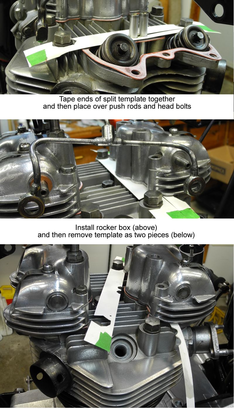
The banjo fittings on the rocker oil feed pipe connect to the rocker spindles with domed nuts. Prior to 1973 the domed nuts were 3/8-26TPI, but they were changed to 24TPI UNF in 1973. If you're having trouble threading on replacement domed nuts, suspect a thread mismatch between the nuts and the spindles.
The WS Manual gives a torque spec of 22 lb.ft. for these nuts, but see below.
Always anneal the four copper washers before replacing them, even if you seal them:
A recipe for a non-leaking rocker oil feed pipe from the TRV7R - Man with the touch, on TriumphRat.net
"I don't go 22 lb on torque on these. It just seems too tight. I do it by feel. I've had practice though." "Not a bad plan to put some sealant on washers also. Loctite 518 is my sealant of choice, however Hylomar universal blue or any of that family of Hylomar will work good also. Put a thin smear both sides. Wipe hole of washer clean. Hang washer on wire 10 min to flash of solvents in sealer. Handle washer from outside. Assemble & tighten acorn nut. Make sure you don't smear sealant on threads or shaft sliding washer on. Clean box surface, banjo sides, nut face well & dry. Sealant doesn't stick well on oily surface. Wipe off excess quickly."
"If banjo fittings want to spin when tightening nuts, counter hold them on the flats. Don't let them spin & bend tube."
Resources
Hermit.cc Engine Torque Stay Fasteners.
TriumphRat.net
StuartMac on assembling the engine torque stays
Resources
Vintage Bike Magazine John Healy: "Where is your valve seat?"
Britbike.com "
Oversized valves fix deep seats?" A very educational thread!
Resources
Workshop Manual (1969 650cc Twins) Section B15: Remove/Replace Valves
Workshop Manual (1969 650cc Twins) Section B16: Renewing Valve Guides
Workshop Manual (1969 650cc Twins) Section B17: Decarbonizing
Workshop Manual (1969 650cc Twins) Section B18: Reseating the Valves
Install valves, springs, and retainers as shown in the figure at right. Lubricate valve stem before inserting into valve guide. Use a valve spring compressor and apply a small amount of thick grease the split collets to help hold the first one in place while inserting the second one. Cover with a rag or take other precautions to prevent collets from flying off to parts unknown should they not be engaged by the top cup when spring tension is released.
Resources
Workshop Manual (1969 650cc Twins) Section B5: Adjusting the Valve Rocker Clearances
Looking at the valve clearance specs for the T120 and for the T140 it may appear as though there is an error, but that is not the case. What accounts for the difference? According to Mr. Pete, "Different cams, with different ramps. No quietening ramp at all on the 3134 cam in the T120."
| Inlet | Exhaust | |
| T120 | 0.002 | 0.004 |
| T140 | 0.008 | 0.006 |
Mr. Pete also made these interesting comments regarding valve clearance:
And these:
It's universally acknowledged that a wee bit too much valve clearance is better than not enough. This is especially true for the exhaust valves. If exhaust valves are prevented from closing, a lack of contact with the valve seats means they are unable to dissipate their heat and the result is burned valves. On the other hand, excessive clearance cause the rockers to 'hammer' the valve stem tips, damaging, and potentially ruining them.
When the rocker boxes or the rocker boxes and cylinder head are replaced with new gaskets (or after head bolts are re-torqued), it's important to re-set valve clearances after a brief break-in of the new gaskets.
The break-in compresses the base and rocker box gaskets as well as the PRT seals, and valve clearance becomes significantly reduced or, commonly, reduced to nil. When that happens engine temperature soars (smokin' hot!), there's a loss of compression and engine power, and then the valves burn.
After a top end re-assembly with new gaskets and a generous preliminary valve clearance adjustment, my first ride is about three miles, one-and-a-half out and one-and-a-half back. Much more than that and she's smokin' hot upon return. Gaskets may subsequently compress sightly after the "milder" break-in, but generally to an insignificant degree.
TR7RVMan alerts us to a potential valve adjustment problem. When removing a spark plug, a fragment of carbon can break off the plug's threads. If it gets trapped in a valve seat it holds the valve open very slightly. Starting the engine after adjustment blows out the carbon leaving reduced or even zero clearance.
Don does say Triumphs are not terribly prone to this, but it can happen. To eliminate the possiblity, he suggests leave the plugs in, or, loosen them one turn, start the engine, blip the throttle one time.
Probably best done on a warm engine just before 12-hour valve adjustment cool down.
Sound can be a useful guide to setting valve rocker clearance (see 'Adjustment by sound and feel', just below), as well as when evaluating correctness of settings with the engine running.
I adjustment of all four valves after removing the gas tank and the air filters. Removal of carburettors is necessary, but whenever they happen to be off it's an opportunity to check valve clearance without their interference.
The lock nuts don't need to be overly torqued, just well snugged down.
The stock Triumph adjustment pins have square heads which make adjustments kind of vague. If you're using the square-headed adjustment pins there is a two-piece valve adjuster tool available. In theory this tool should make adjustment a snap because it allows control of adjustment with thumb and finger while simultaneously tightening or loosening the locking nut. In practice, I found that a poor fit between the adjustor and the square pin was too sloppy for effective control and adjustment accuracy.
Replacement pins are available whose adjustment is made using an Allen wrench or slotted screwdriver. Many, myself included, find these an improvement over the original square-headed pins.
One adjustment technique is to use a ring wrench on the lock nut and a screwdriver in a slotted adjusting pin and use the interplay between tightening and loosening the wrench and the screwdriver to "steer" the adjuster ever so slightly into position for the correct clearance.
Valve clearances should be set to .004" for exhaust and .002" for the intakes. A common method of obtaining 'ballpark' settings is to run the adjustors in until they just contact the valve stems by feel, and then back them off 1/8 of a turn for exhaust, and 1/16 turn for intake.
Another common adjustment method is to grasp the rockers with thumb and index finger and rock them up and down:
Please Note the Following:
In order to adjust a valve's clearance, the valve must be fully closed. The Workshop Manual method is:

So, to adjust the TS intake valve as shown in Step 1 above, close it by opening the DS intake valve (rocker adjuster down):
Do NOT place finger anywhere but on TOP of the rocker - getting a finger caught between the rocker and the rocker box would be like having it in a guillotine!
Lunmad has another method of positioning and adjusting valves.

Note: This section reworked 7 August 2025 to correct errors in text
If you examine the WS Manual and Lunmad methods carefully you'll see that the two methods can be combined into one.
The Combined Method:

This method should work fine for 650 Unit engines with stock cams.
When the cylinder head has been removed and replaced, valve clearance needs to be re-adjusted several times due to gasket 'crush'. Adjust:
Resources
TriumphRat.net "72 T120RV When is a little too much" Don fills in the finer points of making a compression check.
YouTube Lunmad: Compression Test
Testing engine compression is a quick and easy way to determine an engine's general health with regards to valves, rings, and cylinders.
I've always used these five steps, but for better, more accurate results check out Don's method in the post just above.
Five easy steps:
If compression is low, add small amount of oil to the cylinders and retest.
If valves are suspected, check to ensure there is adequate valve clearance to prevent valves from closing fully.
Resources
BritBike.com "
1969 T120R magically loses compression"
A sudden loss of engine compression can result from gas washing the pistons.
Once, after sitting unused (very rare) for ten days, the Bonnie seemed to give up all compression after the first kick. TR7RVMan on BritBike.com correctly diagnosed the problem and offered a solution which consisted of pouring a couple of tablespoons of oil down the plug holes, kicking over the engine several times with the plugs out to remove excess oil, replacing the plugs, and starting as usual. The method worked perfectly and normal compression was restored as soon as the bike started.
Resources
Hermit.cc "Hermit's Illustrated Ignition Timing with Points" Complete illustrated instructions for static and dynamic timing with the 6CA breaker points assembly used on 1968 and later Triumph 650 twins.
Workshop Manual (1969 650cc Twins) Section B28: Removing & Replacing the Contact Breaker
Workshop Manual (1969 650cc Twins) Section B29: Ignition Timing - Initial Procedure
Workshop Manual (1969 650cc Twins) Section B30: Static Timing Where No Stroboscope is Available
Workshop Manual (1969 650cc Twins) Section B31: Ignition Timing by Stroboscope
TriumphRat.net "Thunderous backfire on every kick" Don details many finer points on setting ignition timing with 6CA breaker points assembly (1968 and later Triumph 650 Twins). A must read!
TriumphRat.net "Timing/Points/etc." Don tells you how to set up earlier 4CA breaker points assembly used on 1963-1967 650 Twins.
TriumphRat.net "Points Timing Question" A lot of detailed info on points timing and the AAU.
Britbike.com "Anyone still running points ignition?" Lots of love for points here, but only a couple of good pointers.
YouTube.com Lunmad: Ignition Timing Note that the timing mark on Lunmad's 650 rotor corresponds to TDC. On Bonnie the timing mark corresponds to 38
degrees BTDC. As mentioned by Lunmad in the comments section, use the flywheel locator tool to determine which location the timing mark on your bike's rotor represents.
For clearly illustrated instructions on setting ignition timing with points see "Hermit's Illustrated Ignition Timing with Points". Also be sure to read TR&RVMan's superb posts on ignition timing using the 4CA and 6CA breaker points assemblies - links just above in Resources.
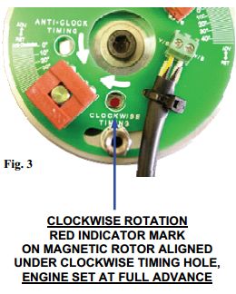
Use a flywheel locator tool (OR timing pointer and rotor timing mark if the one on your rotor points to 38 degrees BTDC and not TDC) to locate 38 deg advance.
Use strobe on either cylinder for dynamic timing
The timing pointer in the primary chaincase cover on later model 650s is basically a short nail - a flat head on one end a pointer on the other. It is a press fit in the primary cover.
If you need to remove or replace the pointer you can drive it out from the inside, but be sure to back up the cover and use great care to avoid cracking the primary chaincase cover.
If the cover is installed on the chaincase before screws are inserted, mating the first screw to the threads in chaincase can be annoying. Easier to find the hole by inserting the top screw in the cover and fitting both together dangling from a Phillips screwdriver.
Use Metric M8 bolt threaded into rotor.
Resources
Workshop Manual (1969 650cc Twins) Section H3: Sparking Plugs
Triumph Service Bulletin #12-68 "Spark Plug Cross Reference Chart"
NGK-spark plugs.jpg Trouble-shooting Dry & Wet Fouling of Spark Plugs
Onallcylinders.com How to Read Your Spark Plugs
Used NGK for quite a while, but have returned to using Champion N3C (new Champion designation 801).
Plug gap: .025".
Interpreting NGK plug designations:
B= 14mm plug thread
7 = Temperature range
E = 19mm plug thread reach
S = Standard super copper core electrode
The higher the NGK number, the colder the plug
The lower the Champion number, the colder the plug
Resources
Workshop Manual (1969 650cc Twins) Section B13: Removing and Replacing the Exhaust System
TriumphRat.net "Exhaust Leak?" Sealing the exhaust pipe crossover
If you don't have a crossover pipe and you don't fit the muffler strap, you can remove the exhaust pipes and mufflers as a unit: remove or loosen the exhaust pipe clamps (7/16"), the exhaust pipe engine bracket (Phillips screws and 7/16" nuts), and the muffler hanger bracket nuts/bolts (1/2").
The nuts holding the chrome exhaust brackets to the engine are 5/16" BS, but it's not necessary to remove them.
When removing and replacing the exhaust pipes on the exhaust pipe adaptors, I find it's ok to hit them with a plastic mallet using a thick, folded rag as padding.
I have Bonnie's original headers with crossover pipe in inventory, but I replaced them (several times - I've seen the gravel and the damage done) with separated headers.
Not running headers with a crossover, I don't have the problem of sealing exhaust leaks there, but apparently this can be a problem, especially with reproduction parts. Don's method takes the guesswork out of centering the crossover pipe to cover the slots in the stubs on the headers, this and other good tips. See link above.
Loose lips sink ships and loose baffles rattle. A loose baffle can be re-welded, but it requires drilling an access hole on the inside of the muffler where the baffle is loose. Afterwards, the hole gets welded shut. Makes an effective and virtually invisible repair.
It has been suggested that loose muffler baffles could be a result of not installing the muffler brace ((70-5676, Ref.27 Fig.15 Page 41 #7). Probably some validity to this. I wonder how many people actually fit this part?
Resources
Workshop Manual (1969 650cc Twins) Section C: Transmission (TOC)
Triumph Overhaul Manual Transmission, Remove & Inspect
Triumph Overhaul Manual Transmission Assembly
Clutch, figure and part listing
Primary Chaincase, figure and part listing
BritBike.com
'Unit 650 clutch thrust washer' Clutch thrust washer discussion, inc. types & changes in size.
TriumphRat.net Discussion: 6-plate VS 7-plate plus springs A whole lot of info here on Triumph 650/750 clutches.
TriumphRat.net TR7RVman's clutch tips Restoring & maintaining the Triumph clutch.
The primary chaincase houses the transmission, which consists of the engine sprocket, the primary chain, and the clutch assembly. The transmission's job is to transfer energy from the engine sprocket to the gearbox mainshaft, the gear cluster, and subsequently to the gearbox sprocket and rear wheel.
See Lubrication Schedule, Primary Chaincase
If you're having difficulty removing the primary chaincase cover, see the BritBike.com post "Primary Case Removal" - resource link just above.
The Britbike.com thread "Primary Chaincase Gasket" (resource link just above) will probably satisfy all your needs concerning the subject - Five-Star thread.
The stock screws holding on the primary chaincase, gearbox, and timing chest covers are not Phillips - they are Posidrive screws. If you don't have a Posidrive screwdriver, pick one up and you'll be amazed at the difference it makes to use the proper tool. And, you won't be damaging the Posidrive screw heads.
A perennial tip is to put gasket sealant on the side of the gasket that goes to the cover and grease the case side so you can remove the gasket intact with the cover and reuse it. I tried that once and found removing the cover and attached gasket was tricky, but perhaps it was because I didn't trim the interior excess gasket material.
The primary chaincase inner cover plate (70-7037, Ref.7 Figure 11 RPC#7) sits behind the clutch on the rear of the primary chaincase. It's held in place by six machine screws and sealed by a gasket.
Do not over-tighten the machine screws holding the trap-door in place. The case there is not so thick, so not an abundance of thread. The screws don't need to be tightened more than a little snug. My Bonnie has one stripped screw hole in the case - I turn the screw in until it's seated and then put a little smear of basic black sealant over the head - never moves, never leaks.
The center hole in the cover plate has an oil seal through which the mainshaft passes on its way through the gearbox sprocket and into the gearbox.
Over the years Triumph used three different methods to seal the trap-door's center hole. The trap-door and it's oil seal must match the method used by your bike.
The side of the plate facing the gearbox has a curious little "pip" cast into it. As noted by TR7RVMan on TriumphRat, if the pip is installed at six-o'clock, it can assist in the plate's removal by prying between it and the gearbox sprocket with a screwdriver. Apart from that the orientation doesn't matter.
Resources
Workshop Manual (1969 650cc Twins) Section C2: Adjusting the Primary Chain
Side-by-Side photos illustrating Primary
Chain Wear When adjusting 'slipper' becomes too arched replace the chain.
Primary Chain adjuster This thread relates to a T140, but includes a lot of info that also pertains to the 650s as well.
The WS Manual method to check wear in a primary chain:
Excessive tightness of the primary chain can damage the DS crankshaft bearing, the chain tension slipper, clutch components, and/or the gearbox mainshaft and its bearing. Conversely, too much slack can give rise to some bad-assed noises from the primary chaincase, not to mention damage to the stator or the primary case itself due to rubbing.
In one place the WS Manual specifies 1/2" total up-and-down slack, but a different section says 3/8". Since a chain's slack often varies from one point to another in its rotation, the two specs might be taken together as the acceptable range. Always check chain slack all around the chain, marking tight and loose spots with chalk before adjusting as necessary.
In order to adjust the primary chain tension, the oil must be drained from the primary chaincase, so it's only logical to check the tension at each oil change and adjust if necessary.
Primary chain tension adjuster D2108
into the drain hole.
Service bulletin 1-69, January 27, 1969)
What I've found is that when chain tension is correct, running the adjuster in one turn will make it too tight and running it out one turn will make it too loose. So when adjusting the tension I look for the sweet spot that way.
Resources
Workshop Manual (1969 650cc Twins) Section C3: Removing and Replacing the Primary Cover
Workshop Manual (1969 650cc Twins) Section C4: Removing and Refitting the Clutch Plates
Workshop Manual (1969 650cc Twins) Section C5: Inspecting the Clutch Plates and Springs
Workshop Manual (1969 650cc Twins) Section C8: Removing & Replacing the Stator & Rotor
Workshop Manual (1969 650cc Twins) Section C9: Removing & Replacing the Clutch & Engine Sprockets
The clutch assembly, engine sprocket, and primary chain are removed simultaneously as one after slacking the chain and removing the stator and rotor.
Exploded figures with parts numbers and specs:
Primary chain tension adjuster D2108
Wheel Puller
Engine Sprocket Puller)
clutch pressure plate spring adjustment tool
clutch locking tool & a 7/8 socket and breaker bar.
clutch center extractor is often mistakenly used as a clutch hub puller. A puller it is not and used as one likely as not ends up with stripped threads (doesn't everyone have one in their collection?). But better a $15-20 tool than a $120 hub!
The clutch hub extractor is an extractor, not a puller. Because the extractor's
outer threads do not engage very deeply with those of the clutch hub. attempting to forcefully tighten the extractor's center bolt against the mainshaft until the clutch hub pops off usually results in stripping out the extractor body's outside threads.
sheared the key and spun on the mainshaft.
Yet another thing learned on the TriumphRat.net Classic-Vintage-and-Veteran-Forum - use end cutters to remove a key stuck in a gearshift mainshaft.
Resources
Workshop Manual (1969 650cc Twins) Section C10: Inspection of the Transmission Components
Workshop Manual (1969 650cc Twins) Section C5: Inspecting the Clutch Plates and Springs
According to Don on TriumphRat.Net, a genuine Triumph clutch stack will measure 'very close' to 1.400", while an Aerco 7 plate clutch with all new steels will measure 1.380".
Resources
Workshop Manual (1969 650cc Twins) Section C7: Renewing Shock Absorber Rubbers
YouTube Lunmad "Fitting cush-drive rubbers Triumph Bonneville T120R"
YouTube Raber's Tech Tips, Episode #4 "
Triumph Unit Construction Twins Cush Rubber Installation"
Resources
Britbike.com John Healy: Thrust washer/clutch center compatibility
Britbike.com
'Unit 650 clutch thrust washer' Thrust washers - types of & changed sizes
Hermit.cc Early and late clutch hub/thrust washers
1963-69 Triumph 650s came with the 57-1734 clutch hub and its 57-1735 thrust washer. That duo was upgraded beginning in 1970 to clutch hub 57-3929 and thrust washer 57-3931. The newer combo is a recommended upgrade for older machines.
The hubs and their respective thrust washers are not mix-and-match: the thrust washer inner diameters are different. Check the part number on your hub and be sure you use the thrust washer that is compatible with it.
| Years | Hub | Thrust Washer | ID | OD |
| 1963-1969 | 57-1734 | 57-1735 | 1.84" (1.88) | 2.62" |
| 1970- | 57-3929 | 57-3931 | 2.035" (2.02) | 2.62" |
| ID in parenthesis from Klempf's British Parts | ||||
You can verify whether a thrust washer is compatible with a clutch hub - the thrust washer's inside diameter should fit the matching recess in the hub.
Both thrust washers (57-1735 and 57-3931) are, or were, available in different materials:
Additionally:
For thrust washers with one side copper and one side steel, place the copper side towards the clutch basket.
The spec given by the manual for thrust washer thickness is .052/.054". Some vendors supply thicker washers, but there are reports that too-thick a washer can make the clutch pack lock up when the clutch center locking nut is tightened.
Resources
Workshop Manual (1969 650cc Twins) Section C9: Removing & Replacing the Clutch & Engine Sprockets
Workshop Manual (1969 650cc Twins) Section C8: Removing & Replacing the Stator & Rotor
Workshop Manual (1969 650cc Twins) Section C4: Removing and Refitting the Clutch Plates
Workshop Manual (1969 650cc Twins) Section C3: Removing and Replacing the Primary Cover
For further information on clutch hub, center, and roller compatibility and assembly, see Notes on Assembling Clutch Hub, Rollers, and Clutch Center
On later models sharing oil between primary chaincase and crankcase, avoid wheel grease as it contains fibers that could harm the shell bearings - use lithium grease instead
If the original 1969 clutch hub (57-1734) is upgraded to newer hub 57-3929 (recommended), be sure to use the matching thrust washer. See "Clutch Hub & Thrust Washer Compatibility" discussion just above, and click here for photos showing clutch hub and thrust washer compatibility.
| Component | Earlier | Upgrade |
| Clutch Hub | 57-1734 | 57-3929 |
| Thurst Washer | 57-1735 | 57-3931 |
The duplex chain sprocket, with its clutch hub, rollers, and clutch center, is installed simultaneously with the engine sprocket and primary chain. If you can do this while juggling several wrenches you could be on the Ed Sullivan Show.
Naturally the DS crankshaft oil seal must be installed before installing the engine sprocket. Click here for details on installing the oil seal,
Getting the clutch hub over the key can be a real pain! It helps to tip the duplex sprocket and clutch assembly slightly forward and eyeball down the clutch assembly's keyway. Kevin paints the key bright yellow and runs a trace line down the shaft. Pointing a flashlight down the keyway he can see the yellow key for alignment.
The clutch nut is one of the four places to use Loctite on a Triumph
steel straight edge placed across the engine sprocket boss to see if it aligns with the duplex sprocket boss.
If the sprockets are not perfectly aligned, use shims (70-8038 .010", 70-8039 .015", 71-2660 .030") behind the engine sprocket to align it to the duplex wheel
Triumph upgraded tab Washer 70-3975 to serrated washer 21-7024.
When torquing the rotor nut, be sure to hold the crankshaft using clutch locking plates and not the rear brake and 4th gear. The latter cause part of the applied torque to be absorbed by the clutch shock absorber rubbers, making the torque reading inaccurate (John Healy, Britbike.com)
If you're working on a pre-unit model both the first and last clutch plates are steel, while on unit model clutches the first plate installed is friction and the last plate is steel.
Resources
Workshop Manual (1969 650cc Twins) Section C6: Adjusting Clutch Pressure Plate
TriumphRat Forum Clutch pressure plate adjustment: Peg's method
BritBike.com Triumph Forum
Don's take on pressure plate adjustment
BritBike.com Triumph Forum OEM/After-Market Triumph clutch spring specs, John Healy
Three adjustors permit adjustment of the pressure plate until it lifts and falls evenly and compresses the clutch plates evenly all around.
After initially setting the adjuster nuts flush with the ends of the adjuster screws, use a pressure plate spring adjustment tool to adjust the three pressure plate spring adjustment nuts to eliminate wobble of the pressure plate as it turns.
To check for wobble, pull in the clutch lever to raise the pressure plate and then turn the clutch using the kickstarter. Observe the outside edge of the pressure plate for wobble as it goes around and use the spring adjustors to compensate for unevenness.
You can also screw in the clutch rod pin adjuster to hold up the pressure plate for wobble adjustments - another great idea from Peg!.
Wobble can be gauged by eye, but a pointer is a great help and can be as simple as a piece of coat hanger wire and some duct tape.
After adjustment, make final check is to see that the pressure plate lifts evenly all around when pulling in the clutch lever.
Properly adjusted, clutch spring tension should be a happy medium between too loose (clutch will slip) and too tight (excessive hand pressure required to operate the clutch and possibility of damage to the clutch rod). If the coils become bound or the spring tension otherwise too high, loosen the three adjustors by small, equal amounts at a time until spring tension is eased and then re-check wobble.
Resources
Workshop Manual (1969 650cc Twins) Section C1: Adjusting the Clutch Operating Mechanism & Cable
YouTube Raber's Tech Tips, Episode #1 - Triumph Unit Twin Clutch Pushrod Adjustment
TriumphRat Forum Don's sage comments on clutchrod's lift adjustment and dragging clutches
The Rabers' video well demonstrates the standard WS method:
The procedure is pretty straight forward, but there are a couple of tips and techniques for best results.
To begin with, it's essential that the clutch cable is completely slack before beginning the adjustment. If not, there's a good chance the 3-ball clutch operating mechanism in the outer gearbox cover will wind up out of its adjustment range - see "
Clutch Operating Mechanism Pops or Clicks" just below under "Clutch Problems".
Stuart gives us a technique to determine exactly when the clutch rod adjustment screw contacts the clutch rod. He uses just a thumb and a finger to lightly hold the screwdriver as he turns the screw in. When the screw and the rod meet the screwdriver will stop.
Guys use different methods to hold the adjustment screw stationary while the lock nut is tightened: many use a screwdriver through a socket and tighten the nut using vice grips on the socket (but be kind to your sockets and use a rag). Those who have one use a special offset hollow-head socket wrench through which they can insert a screwdriver. DMadigan has a very simple and clever method: he simply pulls in the clutch lever to load the screw with tension while he tightens the nut!
Whichever method you use, eyeball the adjuster screw head position before and after tightening down the locknut to be sure it didn't move.
As pointed out by TR7RVMan, new clutch plates will decrease in thickness as they 'bed down', and as the thickness of the clutch pack decreases so does the clutch rod clearance. When the clutch rod clearance becomes less than zero, clutch plates get held apart resulting in the clutch slipping and possibly burning out. So, when adjusting a clutch with new plates, provide slightly additional clearance - something between 3/4 turn and the WSM full turn, and then be sure to check the adjustment regularly until the plates are broken in.
Resources
Workshop Manual (1969 650cc Twins) Section D7: Clutch Operating Mechanism
Fig.9 Gearbox outer cover (Showing ball & ramp parts)
See Clutch Problems, '.. Pops or Clicks' immediately below.
Resources
Triumphrat.net "Grinding into gears - 1972 T120R" Long thread on grimding gears: causes, cures, oils, and accepting fate
If a popping or clicking noise occurs when pulling in the clutch lever it means the 3-ball clutch operating mechanism in the outer gearbox cover is out of its adjustment range. This occurs if the clutch rod is under-adjusted (too much slack) and the cable adjustment is over-adjusted in compensation. That combination of poor adjustment advances the static position of the clutch operating mechanism until normal operation of the clutch lever/cable forces the mechanism past its designed operating range. When that happens the steel balls click and pop as they pass the ends of their ramps.
All that's necessary to correct the condition is to properly adjust the clutch operating rod and the clutch cable as described above.
Possible causes:
You might have heard it said that there's a Triumph part number for the crunching noise a Triumph makes when first gear is selected from neutral at a standstill. All Triumphs make the noise some of the time, and some Triumphs make the noise all of the time, but with perseverance the problem can be eliminated, or at least greatly attenuated.
Although the culprit is usually clutch-related, other causes, including gear oil, are possible. See
Triumphrat.net "Grinding into gears - 1972 T120R" Long thread on grimding gears: causes, cures, oils, and accepting fate
Resources
Workshop Manual (1969 650cc Twins) Section D: Gearbox (TOC)
Triumph Overhaul Manual Gearbox, Remove & Inspect / Gearbox Assembly
Fig.9 Gearbox outer cover
/
Fig.7 Gearbox inner cover
/
Fig.8 Gearbox, gears and shafts
Triumph Service Bulletin #329 "Third gear ratio and selector forks modifications"
Hermit.cc Index to ALL the Hermit Gearbox Articles
Hermit.cc
Triumph Unit 650 4-Speed Gearbox Assembly Made Easy
Hermit.cc
Indexing the Triumph 650 4-Speed Gearbox Made Easy
Hermit.cc The Triumph 4-Speed Gear Cluster, Illustrated and Animated These unique photo illustrations and animations provide a complete and detaied visual understanding of the Triumph 4-speed gearbox operation.
Britbike.com Links John Healy on 4 and 5-speed Triumph gearboxes including leaf-springs versus plungers
Britbike.com
Kevin Roberts' "Upgrading a 5-speed gearbox" Includes excellent photos and informed discussion of Triumph gearboxes.
"Triumph 4-Speed Gearbox Changes" In his deep dive into Triumph unit 650 gearbox components, Mike James provides completely new perspectives on gearbox plunger springs and runs down the raft of changes to springs, plungers, plunger holders, and gearshift camplates from 1968 to 1970. A must-read. (PDF, 8.5mb)
YouTube ClassicTriumph.com - Rebuilding the T160 Gearbox Nicely shot and narrated 5-speed assembly.
Lowbrow Triumph 650 Disassembly & Rebuild: Part 4
Gearbox Disassembly Begins at: 20:45.
Resources
Triumph Service Bulletin #329 "Third gear ratio and selector forks modifications"
Triumph Service Bulletin #8-59 "1969 650s jumping out of 2nd/3rd gears"
Triumph Service Bulletin Trouble-shooting excerpt: "Improper Upshift, Third Gear"
Britbike.com "Gear selection malfunctions after gearbox overhaul" The thread I started on Bonnie's shifting problem
Britbike.com
"69 Bonneville jumping out of gear"
Britbike.com
"T120 unit gearbox problem"
Britbike.com
John Healy: Fix 500s' gearbox jumping out of 3rd gear
Britbike.com "Gear Lever movement" Faulty gear selection thread
Britbike.com "Gear shifter hangs up when down shifting" Don gives us good advice on diagnosing gearbox problems
VintageBikeMagazine.com John Healy: 4/5-speed gearbox conversion Inc. photos comparing 4- & 5-speed components
YouTube Lunmad: Gearbox Video
Triumphrat.net "Grinding into gears - 1972 T120R" Long thread on grimding gears: causes, cures, oils, and accepting fate
Jumping out of gear is not an uncommon problem with the 650 (and 500) gearboxes. My 1969 T120R suffered from the problem for over two years before I found the fix.
Jumping out of gear is often ascribed to gears with worn dogs, but the dogs of my bike's gear set seemed just fine.
Eventually I began thinking that a defect somewhere in the gear changing mechanism might be preventing the gears from being fully engaged to begin with. That idea led to the gear shift quadrant (not to be confused with the inner quadrant - see this Illustration).
Holding the gearbox outer cover gently in a vise with wooden jaws, I affixed a degree wheel to the end of the gear shift quadrant and rigged up a wire pointer set to zero degrees with the gear shift lever in its center position. I then deflected the shifting lever in both directions and recorded the degree readings from the pointer and wheel.
What I discovered was that the gear shift quadrant traveled significantly less when down-shifting than when up-shifting. Were gears sometimes incompletely engaged following down shifts and thereafter prone to "jumping out of gear"?
With a new gear shift quadrant installed in the outer cover I fitted the degree wheel and compared its up and down shift deflections. Barely half a degree difference. Upshift 19 degrees, and downshift 19-1/2 degrees.
Less than one-half a degree doesn't sound like a lot, but when I measured the actual downshift travel of the old and new quadrants I found the replacement quadrant traveled around 3/32" further than the original.
The new gear shift quadrant fixed the problem one-hundred percent. The problem has never reoccurred during the intervening years and tens of thousands of miles.
So the problem turned out to be that the gearshift quadrant's throw was insufficient to dependably push the all the components of the shifting mechanism fully into position. That created an unstable condition prone to jumping out of gear when exposed to stresses and shocks.
As shown by the linked illustration above, the shifting mechanism components consist of the gear shift quadrant and its pawls and springs, the inner quadrant, the shifting forks, the camplate, and the index plunger with its spring.
In Bonnie's case, the gearshift quadrant's travel was too short, but it's also possible for things to get pushed a bit too far, again setting up an unstable condition prone to disengaging under stress.
Resources
Some say an outer gearbox cover gasket can cure certain gearbox problems. Possibly, but forum concensus leans to probably not. I tried one once. No effect in that case. Only time i ever used a gasket. Bonnie didn't come with one and sealant is all that's generally necessary. Hylomar Blue is excellent and just made for this application.
Removing the tapered pin holding the kickstart lever in place is not always so easy. The pin gets bent out of shape by the force of repeated kickstarts, effectively jamming itself in the bore. It sometimes helps to jam the kickstart lever forward using a plastic mallet and then whack the pin smartly against the nut threaded flush.
As noted in the Britbike.com thread above, some kickstart pins are made of harder material than others and they tend to distort less than softer ones.
When replacing the tapered pin, be sure to introduce it from the rear with the kickstart lever in the upright position. Installed with the nut at the rear, the pin fouls the footrest.
Resources
Workshop Manual (1969 650cc Twins) Section D2: Removing & Replacing the Outer Gearbox Cover Assy
The stock screws holding on the primary chaincase, gearbox, and timing chest covers are not Phillips - they are Posidrive screws. If you don't have a Posidrive screwdriver, pick one up and you'll be amazed at the difference it makes to use the proper tool. And, you won't be damaging the Posidrive screw heads.
Resources
Workshop Manual (1969 650cc Twins) Section D4: Dismantling & Reassembling the Gear change Mechanism
Fig.9, Gearbox outer cover (Showing gearchange mechanism
If the quadrant return springs (57-0404) need replacing, TR7RVMan suggests using
T140 springs (57-7051), which are stiffer. They center the gearshift lever better for more positive shifts and ease in finding neutral.
Resources
Workshop Manual (1969 650cc Twins) Sections D3: Dismantling & Reassembling the Kickstart Mechanism
Workshop Manual (1969 650cc Twins) Sections D5: Inspecting the Gear change & Kickstart Components
Workshop Manual (1969 650cc Twins) Sections D6: Renewing Kickstart & Gear change Spindle Bushes
Hermit.cc Kickstarter parts Photos of 1969 T120R Kickstart parts showing part numbers and assembly order
Fig. 8, Gearbox shafts and gears (Showing kickstart mechanism)
Now pay attention because there will be a quiz later: the kickstarter nut at the end of the mainshaft is one of the four places to use Loctite on a Triumph.
Inside the gearbox, the kickstarter shaft rotates a quadrant which engages a pinion gear on the mainshaft. The pinion gear turns freely on the mainshaft, but a small spring permits it to part-time engage a ratchet which is splined to the mainshaft and therefore turns it
The kickstart quadrant has been known to jam against the kickstart pinion. When this occurs it gives the impression of the engine having seized up.
To free the kickstarter, rock the bike forwards and backwards with it in gear.
On the transmission side, the mainshaft connects, through clutch center and clutch plates, to the duplex sprocket, duplex chain, and engine sprocket on the DS end of the engine's crankshaft.
While the clutch lever is in and clutch plates disengaged, pumping the kickstarter lever is to no avail: the clutch center and the steel plates turn, but rotation ends there due to lack of engagement with the friction plates. This action, "freeing the clutch", is performed at the beginning of each riding day as a way to break the "stiction" between the steel plates and the friction plates.
However, supposing the engine doesn't turn over when the clutch lever is out and the kickstarter is depressed? Obviously there's a problem, but where? As we just saw, some parts to the kickstart mechanism are in the gearbox and others are in the primary chaincase so there's only a 50/50 chance of finding the problem by randomly removing one of the covers.
Peg to the rescue with this simple diagnostic:
With the bike on its center stand, engage any gear and depress the kickstarter while holding the rear wheel or applying the rear brake very lightly. If the wheel turns the problem is inside the primary chaincase - most likely a sheared woodruff key fixing the clutch hub to the mainshaft. If the wheel doesn't turn, the problem is with a part of the mechanism located inside the outer gearbox cover - quadrant, pinion, spring, ratchet, etc.
Resources
Workshop Manual (1969 650cc Twins) Section D2: Removing & Replacing the Outer Gearbox Cover Assy
Resources
Workshop Manual (1969 650cc Twins) Section D8: Dismantling the Gearbox
clutch locking tool
will work too)
(1 11/16" socket)
Resources
Workshop Manual (1969 650cc Twins) Section D9: Inspection of the Gearbox Components
The workshop manual doesn't give a spec, but the consensus on forums is that layshaft end play is not so critical as long as there is enough to prevent binding. An end play of .005" is frequently suggested, but anything up to .030" could work o-k.
Two possible methods of gauging end play:
Resources
Workshop Manual (1969 650cc Twins) Section D12: Changing the Gearbox Sprocket
Replacing the gearbox sprocket requires dismantling and reassembling the entire transmission. Before installing a used sprocket, pay close attention to wear and quality.
Sprocket wear and chain wear are contagious. Wear on any component in the final drive increases wear to the others as well. Proper chain maintenance (clean, lube, adjust) will add significantly to the life of a gearbox sprocket, thereby postponing its vexatious replacement.
Hermit.cc Examples of Worn Gearbox Sprockets
Resources
Workshop Manual (1969 650cc Twins) Section D10: Renewing Mainshaft & Layshaft Bearings
Triumph Overhaul Manual Countershaft Sprocket/Mainshaft High Gear Assembly
Removing and replacing the gearbox bearings requires heating their casings. A non-contact infrared thermometer takes the guesswork out of attaining an even 200F/100C temperature. In the absense of such an instrument you can resort to the sizzling spit method.
The mainshaft is supported by two ball journal bearings, while the layshaft runs in a needle roller bearing at either end.
The TS main and layshaft bearings are in the gearbox inner cover.
The DS main and layshaft bearings are in the gearbox case.
Use a mainshaft with a mainshaft high gear as a "stick" to more accurately line the bearing up square with the bore. ( Click here for a photo)
Click here for a photo
Pending Edit
The first two times I replaced the layshaft needle bearings I heated them and used a drift with a heavy hammer. The third time I enlisted the help of a machinist to press them in. Using the plywood
engine base I made and his 50-ton hydraulic press made it super easy.
The specially shouldered drift I had fabricated to install the layshaft needle bearing 57-1606 was supposed to ensure the bearing's correct protrusion (.073-.078") above the gearbox casing, but it turned out to have not been made correctly. Nevertheless, the correct installation was acheived by going slowly a little bit at a time.
I marked the position of the thrust washer locating peg on the casing with a permanent marker to make it easier to align the matching hole in the thrust washer while installing the mainshaft.
Insure that the bearing lip is below the face of the bronze thrust washer.
Pending Edit
The mainshaft high gear and gearbox sprocket must be installed before assembly of the gearbox.
Note that gearbox oil leaking from around the sprocket may be a sign that the DS mainshaft bearing and/or the mainshaft high gear are worn, with the resulting excess play defeating the mainshaft oil seal.
Resources
Britbike.com "
5-speed gears - teeth" In addition to most of the info in the table below, this thread includes a gear ratio calculation spreadsheet posted by John Healey .
"Triumph 650 4 Speed Gear Interchange" JRC Engineering explains incompatability issues between gears produced by the Meriden Triumph Factory and those produced at the Birmingham BSA Factory. Includes charts with specifications and interchangeability.
The following table summarizes the gear ratios and tooth count for Triumph 4/5-speed gearboxes.
Resources
Workshop Manual (1969 650cc Twins) Section D11: Reassembling the Gearbox
Hermit.cc Hughie Hancox Method: The Best! Easy Step-by-Step with Photos
Hermit.cc Side-by-Side Comparisons of Three Methods: WS Manual, Hughie Hancox, & Haynes
I've used several methods to assemble and install the gear cluster and in my experience Hughie Hancox's method is hands down the easiest, surest, and fastest way to do the job.
However you assemble, don't forget to seal the shifter fork shaft and the gearbox sprocket if you expect to not have oil leaks. Seal the shifter fork shaft because its drilling goes all the way through the casing. Permatex and Hylomar have both worked well for me. And keep in mind that after the gear box sprocket is installed, the shifter fork shaft drilling cannot be reached.
The layshaft thrust washers deserve special attention. Their grooved sides face the gears, not the cases, and they should fit well on their locating pegs. To prevent them from falling off the pegs during assembly, put a smear of heavy, sticky grease on the sides facing the cases to stick them there. Avoid greasing the sides facing the gears, that could result in the washers being pulled off their pegs.
During my first gearbox adventure I ended up reinstalling the gear cluster five times, and the transmission twice. The first time I put the cluster in it took just under two hours. The fifth time it took less than three minutes.
At that time I tried three different ways to install the gear cluster. Of the three, I found the WS Manual method (see Method 3, below) of installing the gear cluster as a unit to be the easiest. The only way I deviated from the WS Manual was to index the quadrant and camplate in 1st gear instead of using neutral between 2nd and 3rd as shown by the WS Manual (see "Indexing the Camplate & Quadrant " below.
The next time I reassembled the gears I used the method shown by Hughie Hancox on his DVD, in which he puts the gears in place one at a time. I made several dry runs and could hardly believe how easy this method is.
The one thing I did differently from Hancox was that I did not pre-install the mainshaft and kickstarter assembly in the inner cover the way he does in his video. Instead I inserted the mainshaft by itself before putting on the inner cover and then the kickstarter parts. Next time I'll be inclined to pre-assemble the way Hancox did simply because that way the kickstarter nut can be tightened (45lbs) while the shaft is held in a vise.
When I re-assembled the gears for the fourth and final time I used the method shown in the WS Manual, i.e. introducing both mainshaft and layshaft with all their parts and the shifting arms as a unit. With enough patience it does work. While the WS Manual shows the mechanic inserting the entire assembly without the rod upon which the shifter arms travel, I achieved assembly with the rod inserted through both shifting arms.
When inserting the cluster, first tip the cluster clockwise a bit to get the roller on the mainshaft gear shifter into the camplate. Then, going in further, tip the cluster counter-clockwise to get the layshaft gear shifter's roller into the camplate. The last time I did it the whole thing took less than three minutes.
I saved the best for last! Hancox assembles the layshaft, layshaft gears, and mainshaft gears in situ before inserting the mainshaft, already installed in the inner cover, through the mainshaft gears.
Nearly everyone who tries this method agrees that it is the easiest and fastest of all. For photo-illustrated step-by-step instructions, follow this link:
Hermit.cc Hughie Hancox Method: Step-by-Step with Photos
The thrust washers at either end of the layshaft are held stationary by hardened steel locator pegs in the casing that match holes in the thrust washers. Occaisionally a thrust washer will come off its locator peg and that usually results in either the peg or the washer getting ground down. Here are some descriptions of the problem with details on replacing damaged pegs.
Britbike.com
"Layshaft thrust washer guide pin 76 T140"
Britbike.com
"57-1607 Thrust Washer Missing on 66 T100SR"
TriumphRat.net "Gearbox problem"
TriumphRat.net "T140-gearbox-thrust-washer-problems"
When the Bonnie's locating peg for the DS thrust washer became damaged, I took the engine to the best machinist around and he fabricated a jig which he used to drill a new hole for a replacement peg.
Hermit.cc Locating Peg Repair
The best way to avoid the washers falling off their locating pegs during assembly is to apply some thick, sticky grease to the backsides to stick them to the case. The plain sides of the washers face the case while the grooved sides face the gears. Keep the grooved sides clean and grease/oil free so they don't stick to the gears and pull the washers off the pegs.
Resources
Hermit.cc "Camplate & Quadrant Indexing" Step-by-step descriptions & photo illustrations for three indexing methods
If using the
updated 57-4055 camplate (1970) in 1968 or 1969 cases, be sure to check for sufficient clearance between the top of the plunger holder and the camplate in all positions. It may be necessary to remove material from the top of the holder. For more details and photos, see Appendix 7 on page 18 of Mike James' article "
Triumph 4-Speed Gearbox Changes".
If the inner cover of your gearbox has been removed, the gearshift camplate and the inner quadrant must be reindexed during reassembly.
Indexing the gearbox camplate and quadrant is a procedure that insures that the teeth of the gearshift camplate and the teeth of the inner quadrant are correctly positioned relative to each other as the inner gearbox cover is pushed on.
Indexing the camplate and the quadrant correctly is essential to proper gear shifting operations. Being one or more teeth off in either direction will result in faulty gear shifting and/or one or more gears being inoperative.
Hermit's article "How to Index the Triumph 650 4-Speed Gearbox" includes all the info you need to successfully index your gearbox - complete instructions and clear, detailed photos for every step.
Indexing can be accomplished with the camplate set in any one of three positions: 1st gear or 4th gear (both shown below), or in neutral between 2nd & 3rd (not shown below, but easily interpolated from 2nd and 3rd gear positions as straight up and down).
If an oil filter head is installed on the down tube, be sure to install the lower forward engine mounting bolt through the back of the inner cover before putting the cover in place. Once the inner cover is in place, the filter mounting bracket prevents inserting the bolt from the back. If the bolt is installed head out, it interferes with the oil lines on the inside.
Resources
Workshop Manual (1969 650cc Twins) Section E1: Removing and Replacing the Fuel Tank
Wisc.edu "Bruce Hamilton: "FAQ: Automotive Gasoline" (inc. bibliography)
TriumphRat.net "How to protect the petrol tank"
BritBike.com "
Best Tank Sealer"
BritBike.com "
Triumph paint thread" R Moulding's excellent paint thread, illustrations and discussion
TriumphRat.net Tips on installing knee pads on gas tank
MotionPro.com "Stepless Ear Gas Line Clamps"
When installing the gas tank, tighten the rear mount first. If the front nuts are started first it makes the gas tank lift up in back. This may be why so many Triumphs have stripped threads in the rear frame mount. They were stripped on three out of three of my Bonnevilles - with two of them coming that way to me. Now I use a large tie-wrap over the tank's rear mounting tab (bolt and all rubber parts in place) and through the sidecar mounting hole.
Not all Bonnies are the same, but on mine I tighten the front mounting nuts incrementally from side to side to make sure I end up with an equal spacing between the frame and either side of the tank. We don't want to crush cables or the headling wiring harness.
Neither leaving the gas tank full of fuel over the winter or emptying it is the best way to prevent rust in you tank. See the Resources link "How to protect the petrol tank" above for a discussion of what guys do with their tanks in the winter.
After reading through this TriumphRat
fuel line thread I decided, for safety reasons, to switch from classic look reinforced plastic lines to rubber hose. Not only are plastic lines more prone to leaking, in case of a fire they will melt and add gas to the flames.
When removing carburettors it is only necessary to disconnect the fuel lines from the gas taps. The carbs can then both be removed as a unit without disturbing the rest of the fuel line connections. Likewise, when tearing down the carbs, one can simply unscrew both banjo bolts and remove them and the fuel lines as a unit.
The brass gas tap fuel line connectors shouldn't be so tight that they can can't be loosened by a few light raps with two or three fingers on a wrench. Avoiding over-tightening prevents the gas tap from turning and possibly breaking the seal to the tank.
BritBike Forum Discussion: "
Sealing Gas Taps", Discussion of various sealing washers and methods of making leak-free connection between gas tank and gas taps. In addition to some good insights, this thread includes some funny ripost, some blowing off of steam, and, briefly, some party-line-like communication.
TriumphRat.net Forum thread: "Fuel Petcock Rebuild", Happyfeet rebuilds and lubricates original petcocks - some patience required.
Resources
Workshop Manual (1969 650cc Twins) Section B7: Concentric Carburettor Type 900 (Illustration)
Workshop Manual (1969 650cc Twins) Section B8: Removing and Replacing Carburettors
Workshop Manual (1969 650cc Twins) Section B9: Stripping and Reassembling the Carburettor
Workshop Manual (1969 650cc Twins) Section B10: Inspecting the Carburettor Components
Workshop Manual (1969 650cc Twins) Section B11: Carburetter Adjustments
Workshop Manual (1969 650cc Twins) Section B12: Twin Carburetter Arrangement
Amal "Hints & Tips for Amal Mk1 Carburettor"
Triumph Service Bulletin #2/73 "Checking & Adjusting the Amal Concentric Float"
VintageBikeMagazine.com John Healy: "Amal Concentric Carburettors" (2017)
SquareSpace.com
John Healy: "Tuning Your Carburettor" (2013)
Jba.bc.ca Jim Bush: "Bushman's Carb Tuning Secrets"
BritBike.com
"Bonnie carb jetting help needed" (reading spark plugs w. illustrations)
Triumphbonneville120.co.uk "Amal manuals for Monobloc & Concentric (inc. Premier) carbs"
VictoryLibrary.com Jeffery Diamond: "Super-Tuning Amal Concentric" (Advertisement for booklet)
AmalCarb.co.uk "Notes on Rebuilding the Mark-1 Concentric Carburettor"
OldBritts.com "Amal Concentrics, How they Work and Tuning"
BritBike.com "Motor dies just as I take up throttle cable slack" Electrical or Carb? Informative thread
BritBike.com "Pin gauges for needle jets" Long, informative thread on needle jets
TriumphRat.net "Variations within the 930 Amal Concentrics" TR7RVMan describes Amal Mk1 & Premier differences
TriumphRat.net TR7RVMan offers some good tips on cleaning carbs
YouTube Raber's Tech Tips, Episode 6: Triumph 1971 T120 Bonneville Amal Carb O-ring Installation
YouTube Lowbrow Customs - Amal Carburetor 101 & Throttle Cable Install. Overview, Disassembly & Basic Tuning
The stiffness of these small o-rings makes getting them on difficult. Make the job a little easier by warming the o-rings in hot water and then rolling them on.
Resources
YouTube Raber's Episode #6 Video
Hermit.cc Triumph 650 Carburettor Mounting Methods 1966-1970+
The Triumph parts manuals show several different o-ring set-ups for use between the Concentric carb body and the T120R carb adapters. The #6 1968 parts book lists a thick o-ring (Amal 244/1048) used in conjunction with an insulating block and joint washer. The #7 parts book for 1969 shows a skinny o-ring (622/101 99-0552). The 1970 parts book deletes the insulating block and joint washer and introduces a new thick o-ring (70-9711).
Although the 70-9711 o-ring doesn't appear in Triumph's parts books until 1970, it was actually introduced sometime in late 1968. My Bonnie, an early 1969 model, was fitted with the 70-9711 thick o-ring, and not the thin 622/101 shown in #7. The 'Mounting Methods' table (link just above) summarizes the parts book listings for Triumphs between 1954 and 1970.
While the thin Amal o-ring was used most often in conjunction with an insulating block (E2968) and a joint washer (NA43A), the thicker 70-9711l o-ring is used solo, without joint washer or insulating block. The thin o-ring relies on the insulating block to reduce heat transfer between the engine and the carburetter, while the thick ring reduces heat transfer by creating an air gap between the engine and the carb.
In addition to being a more efficient heat insulator, the thicker 70-9711 o-ring reduces the chance of warping the carburetter flanges caused by uneven or over-torquing the carburetter's mounting bolts.
A small dab of grease helps keep the o-rings in place while offering the carburetter to the mounting studs. Don't use too much grease or the o-ring will migrate as you tighten down the flange.
Kadutz passes on a suggestion that works even better than grease - "
a drop of RTV Silicone".
Next it's finger yoga putting on the rubber insulating rings, cupped washers, and lock nuts, all the while holding the carb ever so slightly off the adapter so the nuts will clear the casting around the ticklers as they are started. Once the self-locking nuts are started, tighten them evenly from side-to-side until there is a .040" to .060" gap between the carb flanges and the adapters.
Resources
The pilot jet (not removable) has a very small diameter and can easily become clogged. Difficulty starting and poor idling can be symptoms of a clogged pilot jet. See " Cleaning Pilot Jet" below.
Standard cutaway is 3. Bigger number=Larger Cutaway=Weaker Mixture.
Amal Concentric Carburettor Modifications, mid 1969.
In mid-1969, Amal modified Concentric carburetter needles, needle jets, and jet holders in order to improve their low and midrange performance. The changes are summarized in the following table.
| Needles | Needle Jet | Jet Holder | |
| Pre-Mid 1969 | 2-9/32" long One ring | 11/16" long | 3/4" long |
| Post Mid-1969 | 2-21/32" long Two rings | 13/16" long Cross-drilled | 7/8" long |
The needle is notched to be adjustable up and down using a clip. The default position for a standard 3-notch needle is the middle notch. Raising the needle enriches the mixture, lowering it makes it leaner.
Concentric needles are .0985" in diameter, and being made of steel, wear slowly, unlike the jets, which are made of soft brass and wear out more quickly.
According to John Healy, Amal supplied 5 needles for the MKI Concentric and they can be identified by thin annular grooves located above the three needle clip grooves:
One way to check jet wear is with go and no-go pin gages. The correct gage sizes for a .106" jet would be .1058"(go) & .1062"(no-go).
I've read on BritBike.com that pin gages can be had for about $3 each on Amazon, but I was unable to find the required sizes there. I ended up contacting Vermont Gage directly and they directed me to their online "Distributer Finder". From there I contacted Russell Supply in Burlington, Vermont and they sent me the two pins with a convenient pin holder and all in a very nice secure case for $31 plus shipping. Very pleased with these - they've allowed me to accurately assess the condition of the jets in my collection. Many turned out to be quite worn, but some are still perfectly usable.
See link above to Britbike.com needle jet discussion.
WS Manual specifies size 220 main jets, but Bonnie has 190s installed. I don't run on the main jets so much any more.
| Manual | Bonnie | |
| Main jet size | 220 | 190 |
| Needle position Up = richer | 2 | 2 (middle) |
| Needle jet size | .106 | .106 |
| Cutaway | 3 | 3 |
| Idle speed adjustment screw | nom 1 1/2 out | |
| Idle air adjustment (out for lean, in for rich) | 2 1/4 - 2 1/2 |
If your Amals are fitted with chokes and you decide to remove them, Amal makes a blanking screw: Amal part number 4/137. Otherwise the small hole can be filled with epoxy.
Resources
TriumphRat.net StuartMac's easy method to pinpoint float bowl problem
Triumph Service Bulletin #2/73:
"Checking & Adjusting the Amal Concentric Float"
If a carburetter is flooding frequently or, worst case, overflowing fuel, it is likely due to either the float not rising (float holed and filled with gas or hung up on the float bowl gasket) or the float needle not seating well (needle worn out or dirt lodged beneath it).
Another possibility is that the fuel level is simply adjusted too high. That adjustment can theoretically be made by lowering the float needle seat. Tricky, but the Triumph Service Bulletin #2/73 (link just above) is there to guide you:
An easier way to adjust the fuel level in the float bowl is to replace plastic bowls with Amal 'stay-up' floats. In addition to being impervious to the effects of ethenol, 'Stay-ups' have adjustable tangs holding the float needle.
Fuel leaks from the float bowl are sometimes the result of over-tightening the float bowl screws which causes the bowl to warp. If the leak occurs after changing the gasket, or after the bike has been sitting for a period of time with no fuel in the bowl, the leak may cure itself after the gasket has soaked and swelled up sufficiently to make a good seal. I have also stemmed this kind of leak with some Hylomar smeared on both sides of the gasket.
The official remedy is supposedly to flatten the float bowl by gently rubbing it on a sheet of very fine abrasive paper over a completely flat surface. Be aware, though, that removing an excessive amount of metal will affect the height of the float and float needle.
When refitting cable to air slide, don't try to compress the spring against the carb cover, away from the cable end. Instead, pinch the exposed (slack) wire cable with finger and thumb and push the cable (and spring) towards the bottom of the air slide until the cable pokes through the other side. So, compress the spring against the air slide, not the cover.
When installing the needle jet and its clip - that's when to scrunch the spring up against the carb cover, gently hanging the bottom end over and outside the carb body while you drop in the needle and clip.
The newer concentric carbs have a removable pilot jet which makes cleaning them pretty easy. On older Amals the pilot jets can't be removed so they must be cleaned in place.
Formally I used a guitar string to clear the idle jets, but some say this just pokes the dirt back upstream where gas will eventually wash it back down to the jets.
John Healy says to use a #78 drill through the pilot air screw hole to pull the dirt out of the jet and downstream:
"Use a #78 (.016") drill mounted in a piece of hobby brass tubing works the best. If you twirl it between your thumb and fore finger as you offer it, it pulls the swarf downstream of the jet to be washed away by the flow of fuel."
On Triumphrat.net Mick describes the process this way:
"Take the pilot air adjusters out and get a number #78 drill (0.016”) stuck to something like a spray can tube to extend it. Poke the drill (gently) in until you pick up the pilot hole, then twist. Afterwards, blow through with spray carb cleaner, and if possible compressed air."
Resources
Workshop Manual (1969 650cc Twins) Section B11: Carburetter Adjustments
Amal "Parts to Tune Up - Amal Mk1 Carburettor"
Amal "How to Tune - Amal Mk1 Carburettor"
Amal "Tuning Twin Carburettors - Amal Mk1 Carburettor"
TriumphRat.net Getting a base setting for carbs Peg's excellent carb tuning method, start to finish
The Workshop manual explains how to sync carburettors in Section B12: Setting Twin Carbs but forgets to mention final adjustment of cable adjusters.
Here is the basic routine for adjusting low speed mixture, idle, and synchronizing. For more details be sure to read Peg's post above!
With electronic ignitions be sure to ground the disconnected spark plug lead to avoid damaging the EI unit. Alternatively, remove the spark plug, reconnect the high tension lead, and ground the spark plug. Charles at Pazon says it's ok to ground the plug lead - I'm not sure about other EIs, so for them perhaps safer to go with the dummy plug method.
Low, thumping idle speeds (600-800 rpm) sound really cool, but can damage the engine due to low oil pressure to the connecting rod big ends - better to keep idle at or above around 900 or 1,000 rpm.
It's a good idea to open the twist grip and then let it snap shut once or twice in between checking new synchronization settings for the cables.
The next two sections talk about "8-stroking". If you're not
familiar with the term, John Healy
describes it well on Britbike.com.
Gavin Eisler offers this sage tuning tip
on Britbike.com: "At half throttle, if acceleration could be better, no 8-stroking, clean running but slow to pick up maybe spits back as the throttle is opened, that's lean at the needle jet or needle position, try lifting the needle one notch..."
A plug chop is one way to determine the correct main jet size, but there is an alternative. If engine power is flat above 3/4 throttle in top gear, begin increasing the main jet by two sizes at a time until the engine '8-strokes', then go down two sizes. So, to check if installed main jet is correct size, put in a jet two sizes up. If the engine '8-strokes' above 3/4 throttle, the smaller jet is the correct size.
Resources
Amal "How to Trace Faults - Amal Mk1 Carburettor"
Follow the links below to discussions of trouble-shooting.
When diagnosing carburetter problems, it can be extremely time-saving to first fully determine whether the problem is actually carburation or actually electrical. This is not always easy as they can seemingly mimic each other.
StuartMac, on TriumphRat.net, offers us this clever method of finding out -
Carburation? or Electrical?:
Then, go for a ride; if/when the misfire develops, note the rpm and twist grip position; change gear; if the misfire persists, note the new rpm and twist grip position.
Once you're sure the problem is not electrical (but always keeping an open mind!) you can move ahead to carburation. But this is a good time to note that if you haven't yet marked your throttle positions the way StuartMac described, that essential step should probably be your first move in diagnosing or tuning the carb.
Whether you're diagnosing or tuning, observations and advice from veterans like these below will help turn you into a carburetter connoisseur!
Resources
Workshop Manual (1969 650cc Twins) Section B6: Removing and Replacing the Air Cleaners
When using paper air filters, both air cleaners can be screwed on/off intact, but when using wire and gauze filters (thicker than the paper ones) the right-hand unit must assembled/disassembled in place due to interference from the foreword edge of the oil tank.
I prefer the wire gauze units because they are reusable. At first I washed them in kerosene, but now I just wash them with hot water and dish washing detergent. A water-based degreaser would probably work well also.
Good cables last a long time if they are kept well-lubricated. Bonnie's throttle cables have been in service for seven years at the time of this writing and they are still completely serviceable.
My lubrication method is to disconnect a cable at the handlebars, tape its loose end into a funnel, fasten the funnel overhead, and pour in a couple thimbles of 10w or 20w oil to make its way down the cable overnight. Given this treatment once per riding season the cables only need an occasional few drops of oil to ferrules, nipples, and adjustors. And, of course, after exposure to rain.
Standard throttle cables for US bars are 43" - 45" depending on how they're measured.
A throttle cable routing that has worked well is for the TS cable to cross through frame beneath the gas tank to join the DS cable before they both pass between the front forks and up to the twist grip. I'm not sure what the hole in the TS headlight bracket is for, but it doesn't seem to work for the throttle cables.
When I got my Bonnie the throttle cables crossed over between the carbs and the twist grip. That is to say that the TS carb cable was connected to the inboard side of the twist grip and the DS cable went to the outboard side of the twist grip. That makes sense in terms of cable length and the routes taken, but I found balancing the carbs was more intuitive after I reversed the cables so their input and output ends were, so to speak, parallel.
Use oil and not grease to lubricate the twist grip. Grease is too thick and the throttle will 'hang'.
I have successfully routed the clutch cable from the TS abutment on the outside gearbox cover through the frame beneath the gas tank to the DS and then through the front forks. However, I feel there is less friction when the cable arcs forward from the abutment and passes through the space between the gas tank and the forward gas tank bracket on the TS before passing through the front forks. A small cable-tie loosely securing the cable to the forward rocker oil feed pipe keeps everything tidy and in place.
Resources
Workshop Manual (1969 650cc Twins) Section B42: Removing & Replacing the Tachometer Drive
hermit.cc Smith's Instrument Repair Resources
Parts Reference: #7, Fig.33 Page 73 (link just above).
Securing screw 70-9332 has a Left-hand thread
(Ref#17 Fig.33 P.73 #7)
After removing the gearbox from the crankcase always replace Sealing washer (70-7351, Ref.# 33 - same part used for gas taps) as well as o-rings as required.
O-rings used in the tach gearbox are as follows:
Note that if the tachometer drive has been replaced with a tachometer drive plug (21-1871 Ref.25 Fig.2 P.15 #7) on the DS crankcase, it has a left-hand thread also.
Unscrew tach drive plug and add grease after cleaning out as much old grease as possible. When plug is screwed in, excess grease will be expelled at cable connection to drive unit.
See "Tach & Speedometer Cable Lubrication" below.
Resources
Workshop Manual (1969 650cc Twins) Section A19: Speedometer Cable Lubrication
hermit.cc Smith's Instrument Repair Resources
YouTube.com - Crankbuster's "Smiths Magnetic Speedo". Crankbusters Animated assembly of Smiths Magnetic Speedo.
The speedometer cable follows the swinging arm frame and then the main frame all the way to the speedometer head. It is held in place by three cable ties: one in front of the speedometer gearbox on the swinging arm frame, another on the main frame beneath the engine, and one on the frame near the front engine mount.
Because oil can "corkscrew" its way up the inner cable and into the
instrument, Andy Hansen of Vintage British Cables recommends only using grease for lubrication of the tachometer and speedometer cables. And to ensure that no lubrication enters the instrument head, Andy advises us to not put lubrication on the 6 inches closest to the instrument.
After inspecting a new speedo cable I purchased from Andy I wasn't sure if it was adequately pre-lubricated as I could just barely detect a light coat of grease. I emailed Andy and he replied that his cables are indeed pre-lubricated and ready to install. That's when I realized that I'd been over-greasing the cables!
So, apply a very light coat of grease after unscrewing the collet beneath the speedo/tach head and withdrawing the inner cable. When replacing the cable, be sure to verify that the ends are properly seated in the receptors of the speedo gearbox and speedo head.
If you're looking for a replacement speedometer gearbox and find yourself confused as to whether you need a 1.25:1 ratio or a 15:12 ratio, chill out: do the math and you'll realize that they are the same.
Curiously, the WS Manual makes no mention of greasing the speedo gearbox, so don't overlook this crucial periodic maintenance.
Speedo gearboxes are a slip fit on the rear axle. If you have difficulty removing one, it's possible that repeated tightening of the TS axle nut has swaged the gearbox casing, causing it to bind on the axle. In such a case it may help to "unscrew" the gearbox off the axle and then file the hole to its original size. According to Don this problem is more common on OIF models.
Resources
BritBike.com - Don's informative post on trouble-shooting & fixing
speedometer cable problems
A common problem with Smith's speedometers is a wavering or bouncing needle. Most frequent causes are poor cable routing, too much/too little lubrication, or use of too heavy a grease (see cable lubrication, above). An incorrect inner cable length (too short or too long) can also manifest itself this way.
If the speedo is inoperative, an electric drill (very low speed only!) to drive the cable or the speedometer head can be of help in isolating the problem.
Another common problem with Smith's speedometers is extreme stiffness in resetting the trip meter. These may help:
Some say removing the handle and spraying with lubricant or WD40 can fix this problem, but this sounds more than a little shakey to me. As previously mentioned, lubricants findng their way into the head are to be avoided.
Resources
Workshop Manual (1969 650cc Twins) Section G1: Removing the Telescopic Fork Unit (Covers Handlebars)
Triumph Service Bulletin #306: flexible handlebar mounting "Flexible Handlebar Mountings on 650s".
Fig.18 Handlebar mounting, steering damper
Fig.27 Handlebars, control levers, steering damper
BritishCycle.com (BCS)
BCS's Handlebar Chart with Dimensions
Follow link above for the extensive BritishCycle.com British motorcycle handlebar reference, with photos and dimensions.
Late '60s Triumph handlebars are 7/8" in diameter. Handlebar styles I've tried on my Bonnie are:
The Commando bars beautifully compliment Bonnie's lines, the wider USA bars inspire confidence on the gravel, and the UK bars are at home on the concourse.
For the handlebar shock-absorbing mounting to work properly, the parts must be installed in the correct order and the hemispherical washers must be oriented correctly, i.e. with their hemispherical sides facing each other.
It is also important that the hemispherical washers have indents around their inner hole. The indents match the
shoulders on the shanks of the eye bolts and if they are not present the eye bolts can be stressed to the point of
breaking. (John Healy).
The correct order of the parts is listed below and shown in the figure to the right.
If an eyebolt makes contact with the head lug it can create a safety issue. For details, follow link to "Triumph Service Bulletin #306" in the Resources section just above.
Use similar method to install new bushings.
It's been suggested on forums that hair spray can be used to keep handlebar grips in
place. I know from experience what a dangerous idea that is. During dry weather the hair spray works fine, but even the tiniest rain shower turns it super-slippery! My grips were sliding off the bars like the proverbial greased pig - steer clear of this solution!
After the hair spray debacle I tried the old school friction tape method next. Not plastic electricians' tape, but cloth friction tape. The first time I wrapped the handlebar with three layers. That worked well until a spell of very hot weather softened the adhesive and the layers of tape began sliding on each other.
Thinking that possibly less is more, I tried friction tape again, but using a single layer. Much better, but the grip still slides off. Very, very slowly, but it still slides off.
I'm going to try some rubbery hockey tape I have lying around and if that doesn't work I'm going to bite the bullet and get some Three Bond Griplock #1501C this winter. Very pricey, but presumably an effective solution.
As I write this it occurs to me that maybe I should try taking a rasp/belt sander to the handlebar.
Resources
Workshop Manual (1969 650cc Twins) Section E5: Adjusting Rear Suspension
Workshop Manual (1969 650cc Twins) Section E6: Removing & Refitting the Rear Suspension Units
Workshop Manual (1969 650cc Twins) Section E7: Stripping & Reassembling Suspension Units
TriumphRat.net "Shock absorber replacements" inc. comments on Emgo, Ago, Ikon, Fournales
Dealing with the split ring clips at the top is much easier with two sets of hands.
When replacing the shock absorbers, instead of forcing the bushings into place from the rear of the frame bracket or from directly beneath the shock mounting holes, it may be easier to insert the bushings from beneath the spare hole in the forward part of the upper bracket, and then slide (bash with plastic mallet) to the rear and into place.
If the brackes are too tight for replacement shocks, as were Hagons I installed on Bonnie, cut a 5 or 6-inch block of hardwood the width of the brackets and use it to gently prise the brackets a bit wider.
The same bolt (14-0235) is used to fasten both tops and bottoms of the shockes to the frame. Bottom bolts have a plain washer (60-4246) beneath their heads and a lock washer (60-4259) beneath the nuts. According to #7, the bolts on top have no washer beneath their heads and a (different) plain washer (GS308) beneath the nuts.
Top and bottom bolts are shown in #7 with the heads outside and nuts inside. Installed that way, the end of the bolt on the DS may be interfered with by the brake drum cover. If so simply turn the bolt around. Nuts out also makes periodic tightness checks easier.
Resources
Workshop Manual (1969 650cc Twins) Section A16: Telescopic Forks Lubrication
Workshop Manual (1969 650cc Twins) Section G: Front Fork Table of Contents
Workshop Manual (1969 650cc Twins) Section G9: Changing the Front Fork Main Springs
Hermit.cc Photo: Front Fork Components
Hermit.cc Step-by-Step illustrated front fork reassembly
YouTube Raber's Tech Tips, Episode #2 - Triumph 500 / 650 Front Axle Widths
YouTube Raber's Tech Tips, Episode #5 - 1967 Triumph TR6 Front Fork Disassembled
Mike James' Triumph T120 Fork Changes During 1968 & 1969 Model Years (PDF)
TriumphRat.net
Peg describes & illustrates T140 fork seals, 1973-1982. (Scroll down to 2nd post for photos).
Frank said it's "cheating", but gaiters can be replaced by simply removing the front wheel and fender. Pulling the tops of the gaiters past the dust excluder sleeve nuts is quite difficult, but pushing works well - dig the tips of both thumbs right into the top of the gaiter just below the "collar", and PUSH! Makes the job a breeze.
Resources
Workshop Manual (1969 650cc Twins) Section G3: Renewing the Front Fork Seals
Fork oil seal replacement essentials:
to slide seals into place over lightly greased stanchions
For more details, see article "Reassemble Triumph 650 Front Fork Legs".
The correct diameter of the stanchion tubes is critical for proper damping and also for a tight fit in the lower yoke.
As well, the profile and dimensions of the taper at the top of the stanchion tubes must engage the upper yoke sufficiently to prevent the tube from turning when the cap nut is tightened.
Before installing newly-purchased stanchions they should be carefully compared to the specs in the Workshop Manual's General Data section as well as the units being replaced.
Use service tool Z161, stanchion
tube puller to draw stanchion tubes into top lug.
Resources
Workshop Manual (1969 650cc Twins) Section G1: Removing the Telescopic Fork Unit
Remove as a unit to maintain steering head bearings.
Remove separately to maintain fork - oil seals, etc.
Stanchion cap nuts wrench))
Resources
Workshop Manual (1969 650cc Twins) Section G2: Dismantling the Telescopic Fork
Workshop Manual (1969 650cc Twins) Section G3: Inspection & Repair of Fork Components
With the fork legs removed from the triple tree (see "Removing Front Fork Legs Separately"
Dust excluder sleeve nut wrench
Resources
Workshop Manual (1969 650cc Twins) Section G6: Reassembling and Refitting the Telescopic Fork Unit
Reassemble 1968-69-70 Triumph 650 and 500 Front Fork Legs
Step-by-step, clearly illustrated assembly instructions.
Rebuilding the front fork legs is not a terribly big job - it's not necessary to remove the upper and lower yokes from the frame, for example. But using the appropriate special tools, especially the stanchion tube puller, gives a huge advantage.
To refit the complete front fork assembly (including the upper and lower yokes).
Resources
Workshop Manual (1969 650cc Twins) Section G7: Telescopic Fork Alignment
When replacing front wheel and axle, the front fork should be aligned as follows.
Resources
Workshop Manual (1969 650cc Twins) Section A14: Greasing the Steering Head Ball Races
Workshop Manual (1969 650cc Twins) Section G4: Renewing the Steering Head Races
Workshop Manual (1969 650cc Twins) Section G8: Adjusting the Steering Head Races
Britbike.com
Part numbers for cones & cups to replace loose bearings
Lowbrow Customs Tapered roller bearing conversion kit
Britbike.com CBS description of 2-piece drift for installing steering head bearings
The front fork turns on 40 steel balls held by cones and cups, one pair on top and one at the bottom of the steering stem. Before beginning disassembly, spread a cloth to catch any steel balls that may fall out,
After the stanchions have been removed, the top cone/dust cover is removed by loosening the sleeve nut's pinch bolt and unscrewing the sleeve nut. Then, the lower yoke and steering stem can be dropped down and out of the upper yoke and headlugs (neck).
To renew the cups, drive the old ones out of the upper and lower lugs using a long drift. Strike evenly all around the edge against the protruding lips of the cups until they fall out.
A chisel or punch can just get a purchase on three sides of the bottom cone. Several good blows evenly around the three sides should break the cone free. Once a small space between the yoke and the cone has been opened, use two chiseles, one on each side, to wedge the cone free. The steering stem is shouldered where the cone fits, so the cone only needs to move about 5/8" before it is freed and pops off.
Replacing the cups is pretty straight forward. After placing the cups squarely against their steering lugs, use a hammer and hardwood block to drive them all the way in, taking care of course that they go in straight.
There is a special tool (61-6009) to install the lower cone, but the manual says a 9" piece of pipe with a 1-1/16" ID can be slipped over the steering stem and used to drive home the cup.
Removing and Installing the Steering Head Lower Cone Using a Stanchion Tube
Use an old stanchion as a drift to install the lower cone. It turns out that Triumph stanchions have a 1-1/16" ID. An additional benefit of using a stanchion is that once the cone has been carefully lined up sqare to the lower steering lug, the stanchion can be "dropped" onto the cone to get it squarely started. Then place a hardwood block over the end of the stanchion and strike it with a 3 or 4-pound hammer until it seats all the way.
These steps are for installing the upper and lower yokes separately from the fork assembly - for refitting as part of fork assembly, see Refitting Fork Assembly to Frame just above)
In 1969, only the TR6C came equipped with a steering damper. I found the dampers on my '66 Bonnevilles so useful that I retro-fitted one on Bonnie. Very good on bad roads and windy days, just be sure to loosen it when you get into town!
I think wind-induced deviation in down-road trajectory is at least as much due to its effect on the rider as it is the bike. Wind pushing against s rider's upper body moves their shoulders, thereby moving the handlebars with predictable results. A steering damper can eliminate the effect.
When retro-fitting a damper to Bonnie i neglected to fit 'locating pin' 97-2107, which, as i later learned TriumphDave's Britbike.com post, prevents the sleeve nut from falling off.
The steering lock cylinder is held in place by a counter-sunk set-screw. The set-screw hole is covered over by a plug which must be dug out before removing the set-screw and lock cylinder. Bonnie's is fubar, so i never let her out of my sight.
Resources
All Front & Rear Axle Retainers, Support Rings, and Dust Covers Illustrated
For both 1969 Triumph axles, this photo illustration shows both sides of all grease retainers, dust covers, support rings,
backing rings, and retaining rings, with dimensions, part numbers, and RPC reference numbers for all.
Front Axle bearings, covers, rings, and retainers
Photo illustration showing the order and orientation of all front axle parts: dust cover, retaining ring, support ring, grease retainer, bearings, and circlip. Includes part number, size and description, orientation, and #7 and Hermit's parts list references.
Rear Axle bearings, grease retainers, and retaining and backing rings illustrated
Photo illustration showing assembly order and orientation of rear axle bearings, grease retainers, retaining ring, backing ring, and speedometer gearbox. Includes part numbers, parts book references, and descriptions and sizes.
Rear Axle nuts and distance pieces
Photo illustration showing assembly order and orientation of rear axle inner and outer nuts and distance pieces. Includes part numbers, parts book references, and descriptions and sizes.
Triumphs use three different front axle widths, and between 1968 and 1969 the fork was modified in several other ways as well - not all of them compatible with each other, and not all well documented.
Mike James puts the axe to axle changes in
Triumph T120 Fork Changes During 1968 & 1969 Model Years (illustrated PDF)
Resources
Workshop Manual (1969 650cc Twins) Section F9: Wheel Building
Workshop Manual (1969 650cc Twins) Section F10: Wheel Balancing
TriumphRat.net Peg's post on centering rim on hub and working with spokes
Hermit.cc "Wheel Rebuilding by Phone"A first-time experience, by Geoff Collins
Resources
Workshop Manual (1969 650cc Twins) Section F1: Removing & Refitting Front Wheel
Workshop Manual (1969 650cc Twins) Section F: Wheels, Brakes, and Tires Table of Contents
Workshop Manual (1969 650cc Twins) Section F9: Wheel Building
Workshop Manual (1969 650cc Twins) Section F10: Wheel Balancing
Workshop Manual (1969 650cc Twins) Section F14: Sidecar Alignment
TriumphRat.net Replacing Rims - Devon vs Central
Hermit.cc Wheel Bearing Locking Ring Wrench
Nave (knot knave) is a British term for a metal cover of a wheel hub, especially one which is chrome, stainless steel, or otherwise decorative. So, a hubcap.
To remove it, some say have at it with a couple of screwdrivers on the three tabbed spots. But removing the Triumph nave without permanant disfiguration may require at least a bit more finesse than that.
One proposed technique, that I've not tried, but sounds good, is to pry all three tabs simultaneously using hardwood sticks. The tips of the sticks must be whittled down a bit so they engage the tabs positively and either an assistent is required or elbows and knees must be pressed into service.
Resources
Workshop Manual (1969 650cc Twins) Section F8: Removing & Refitting Wheel Bearings
Hermit.cc All the Front Wheel Axle Parts Photo illustration showing assembly order, orientation, part numbers, part number references, sizes, and descriptions of your 1969 (and other) front wheel axle.
Front wheel bearing TS retaining ring 37-0582 has a left-handed thread. (Ref.15 Fig.19 P.49 #7)
Special tool Z76 (61-3694) can be used to remove the retaining ring.
Resources
Workshop Manual (1969 650cc Twins) Section F5: Brake Adjustments
Workshop Manual (1969 650cc Twins) Section F6: Stripping & Reassembling Brakes
Workshop Manual (1969 650cc Twins) Section F7: Renewing Brake Linings
Hermit.cc Front Brake Shoe Illustrated Correct orientation of leading/trailing brake shoe edges and rotation.
VintageBrake.com Tips on renewing and tuning vintage motorcycle brakes
Britbike.com Stuart provides many details on various Triumph hub, anchor plate, & axle setups
TriumphRat.net The Village Idiot, RPW, and others divulge their best brake tuning secrets!
When reassembling the brake, note that:
To adjust the TLS linkage follow these steps:
For more adjustment tips see "brake tuning secrets" link above in Resources.
Resources
TriumphRat.net StuartMac's tips on fitting the front fender stays to fork
To remove the front wheel without disturbing the fender and fender braces, deflate the tire.
The front fender brackets (Ref.5 in Fig.26 Fenders ) fit on the lower fork legs pointing forward with the bottom angle projecting upwards.
The bolts (Ref.23) which fix the stays to the brackets face nuts out (Ref.24).
Figure 26 (#7) doesn't show how the forward and
center stays (Ref.2 and Ref.3) fit onto the fender brackets (Ref.5). They should both be fixed to the outside of
the fender brackets as shown here.
If the fixing bolts are hard to get through the stays and bracket, slacken the bolts holding the stays to the fender and then give the bolts a rap with the plastic mallet.
[The mounting hole for the bottom stay (Ref.4) in Bonnie's used replacement lower fork leg is threaded, so the bolt must be threaded in and out.]
Resources
Workshop Manual (1969 650cc Twins) Section F: Wheels, Brakes, and Tires Table of Contents
Workshop Manual (1969 650cc Twins) Section F4: Front & Rear Wheel Alignment
TriumphRat.net Replacing Rims - Devon vs Central
Resources
Workshop Manual (1969 650cc Twins) Section F2: Removing & Refitting Rear Wheel
Workshop Manual (1969 650cc Twins) Section F3: Removing & Refitting Quickly Detachable Wheel
Either the wheel can be removed by lowering it through a specially-designed service table, or the back of the bike can be hoisted up to provide the required clearance between wheel and fender.
Procedure to remove rear wheel:
Resources
A nut and bolt fasten the front of the chainguard to a tab on the swinging arm frame. Replacement Parts Catalogue (RPC) #7 show the bolt inserted from inside the tab and outwards through the chaingaurd ((Ref.28,Fig.13,P.37 #7)). Some think this is an error.
For starters, oriented that way, the bolt can't be installed or removed while the fender is in place. Even more importantly, the bolt's head should be installed inside the chainguard, where otherwise any protrusion beyond the nut will snag the chain.
If you choose to install the bolt through the chainguard, though, you'll have to deal with the hastle of holding the thin Philidas self-locking nut in place while you start the bolt.
Getting the nut on the bolt through the welded tab on the swing arm to affix the chain guard is a real PITA!. Afix the nut permanently with Loctite red.
When re-installing the rear wheel, one must properly align the speedometer gearbox and then activate the rear brake somewhat forcefully (see "centering brakes below") while tightening the inner axle nuts. To do this the easy way, with the wheel mounted on the bike, you need a very thin 1-5/16" wrench for the TS inner nut. If you don't have a suitable wrench, save lots of trouble and get one.
Before I had the right wrench, I did all the above with the tire in a bench vise. But the problem was to get the speedo gearbox correctly aligned - a very trial-and-error affair. It's so easy on the bike - get the wrench!
Off the bike:
The rear wheel brake shoes should be centered to the axle to prevent the brakes from 'pulsing'. To center the brake shoes, apply the brakes while tightening the inner axle nuts.
This is most easily done with the wheel on the bike because that facilitates aligning the speedo gearbox perfectly, and provides the use of the brake pedal for applying the brakes. But key to performing the work this way is the thin 1-5/16" wrench to tighten that TS inner axle nut.
Brake torque stay (ref 11 page 37) should go on before the plate for passenger foot peg and muffler bracket.
Both ends of torque stay are supposed to use the same nuts (14-0304)(3/8W) and spring washers (PCW73A), but on Bonnie one is thicker front) and one is thinner (rear).
The "C"-clamp on the torque stay adjusts the bottom of the chainguard with respect to the tire and the chain. It must be fit so that it rests ON TOP of the chainguard bracket to allow for adjustment. Bit of a PITA, but fitting the nut and bolt with the passenger peg and mounting plate removed is much easier.
Resources
Workshop Manual (1969 650cc Twins) Section F8: Removing & Refitting Wheel Bearings
Hermit.cc Photo & Drawing of Rear Wheel Axle Parts
Hermit.cc Wheel Bearing Locking Ring Wrench
Sealed bearings are the way to go.
Resources
Workshop Manual (1969 650cc Twins) Section F5: Brake Adjustments
Workshop Manual (1969 650cc Twins) Section F6: Stripping & Reassembling Brakes
Workshop Manual (1969 650cc Twins) Section F7: Renewing Brake Linings
Hermit.cc Rear Brake Shoe Illustrated Correct orientation of leading/trailing rear brake shoe edges and rotation.
Shouldered end of the rear wheel spindle goes to T.S.
See Rear Wheel Axle, Grease Retainers and Retaining and Backing Rings, .
If removing the brake cam lever (Ref 32 Figure 20) from the brake cam post is difficult, try this:
When reassembling the brake, note that:
Brake shoe illustration.
Over time, a Triumph rear brake pedal pivot becomes a loose fit.
This would be an easy fix if Triumph had used a bushing there, but they
didn't. Here's how one TriumphRat.net listee fixed the problem:
TriumphRat.net WOL: "Sloppy Brake Pedal"
With everything assembled, it's nearly impossible to splay the cotter pin that fastens the rear brake rod to the brake pedal lever: therefore, do it at one of these stages of disassembly:
Should the "U-Hook" end of the rear brake return spring come off the brake arm, don't despair. The same "pulling" method used with the center stand spring will also tame this spring. Just make a few loops of cord, hook them over the end of the spring, and hoist it back on with one hand while using the other to hold the brake arm slighly forward.
Resources
Workshop Manual (1969 650cc Twins) Section E4: Removing & Replacing Rear Mudguard
Bracket fits inside the rear frame loop. See TBA photo.
Rear fender bracket on frame 1/2" bolts (same bolt used for oil bottle bracket).
Resources
TriumphRat.net ""Fender Drill Pattern Templates", Good tips on fitting a new rear fender
Note that the two rear fender bracket mounting bolts (14-0113)
(Ref 32 Figure 26)
must be installed before putting on the fender.
Resources
Workshop Manual (1969 650cc Twins) Section C11: Rear Chain Alterations & Repairs
Workshop Manual (1969 650cc Twins) Section A13: Rear Chain Lubrication & Maintenance
Britbike.com
Drive chain lubrication Opinions on chain lubrication - take your pick
Britbike.com
New rear chain Long thread on chain specs/brands with an emphasis on Renold chains
Britbike.com
Final drive chain Regular vs sealed (o-ring) chain and more Renold comments
When lubricating or working on the chain, use a short piece of rain gutter to contain the mess.
If the chain happens to fall off the rear sprocket, it can be replaced by inserting the tapered end of a chopstick through the spokes and into the hole at the end of the chain and using it to drag the chain far enough back to engage the sprocket and be pulled around using the wheel.
The orientation of the master link clip is critical - the closed end of the clip must always be at the front as it travels around in the direction the chain is moving. You can think of the clip as a spawning fish that's swimming up the back of the rear sprocket - but with the flow, not against it.
Replacing a master link on the side away from you is awkward. Instead, insert a spare master link from your side of the wheel - it keeps the ends aligned perfectly and gives tactile reference for installing the actual master link from the opposite side.
Resources
DirtTricks.com ""Measuring Chain Wear", Greg Burns
As Burns points out in his article "Measuring Chain Wear", chains do not stretch, they become longer due to the pins wearing an oblong pattern in the bushes.
When wear progresses to the point the chain is no longer a perfect match with sprocket teeth, wear to both sprockets quickly accelerates.
The workshop manual describes a standard method for checking wear:
How much wear is acceptable? Opinions differ. Extrapolating from 20 links to 100, the manual sets out 1.25" (1-1/4) as the maximum acceptable increase in length over 100 links.
However, Burns claims that "Most chain manufacturers limit chain wear to approximately .006" per link". That works out to .6" max wear per 100 links, or just under half what the manual considers maximum acceptable wear.
Which is right? I incline toward the figure suggested by Burns for the simple reason that a new chain costs less than a new chain and two new sprockets. And a lot less trouble to change!
For asphalt riding I clean and lubricate the chain at each oil change, or every 1,000 miles for Bonnie. When I'm mostly riding the gravel I clean the chain every 500 miles.
Kerosene used in chain cleaning can be reused many times. Simply allow the suspended particles to settle and then gently pour off the clear kerosene into a clean container, ready for the next cleaning.
The rear chain oil feed is a hose from the oil tank to a fixed dispensing pipe that drizzles oil directly on the chain. The rate of flow is regulated by a tapered screw just under the oil tank filler cap. Most riders choose to shut off the oil feed supply and lubricate the chain manually. Adjusting the chain oil feed flow, or eliminating it, is accomplished by closing the adjusting screw all the way clockwise.
In an old pan, immerse the clean chain in heavy (summer) chain saw bar oil for 20 minutes or more. Next, hang the chain overnight to drain excess oil. Next day, wipe the chain lightly with a clean rag before reinstalling.
Pull the clean, lubricated chain back on using an old chain.
On the bike, after a rideAlways lube a mounted chain when it's warm after a ride! Oiling a cold chain just makes a mess on the floor. Applied to a warm chain, oil will penetrate inside the rollers where it's needed instead of dripping off.
Using the tapered tip of a gear oil container, I apply heavy chain saw bar oil to the chain while I spin the rear wheel. It's surprising how much oil a warm chain will "absorb", but don't carried away! If oil drips off a warm chain the application was excessive and the excess will be flung off directly during the next ride. Performed regularly after every ride, very little oil is needed with each application.
Do not over-lube! An excess of oil can seep into the rear wheel brake drum and spoil the brake shoes.
Resources
Britbike.com "
TR7RVMan's take on adjusting rear chain."
Britbike.com "
Rear wheel adjustment" Another thread covering the finer points of rear chain adjustment.
The technical way of adjusting the rear chain is to disconnect the rear shock absorbers, prop up the swinging arm frame in the position where the chain is the tightest, and adjust for 3/4" inch up-and-down slack in the center of the chain's bottom run.
However, there is a shortcut method that will deliver the same result without having to disconnect the shocks.
With the bike on the center stand, rotate the rear wheel until you find the position that gives the most slack in the chain half-way between front and rear sprockets on the lower run. Now, with the chain in its slackest position, use a finger to push the lower run up and down. Adjust chain tension until the up and down chain slack is 1-3/4". That adjustment is the equivalent of setting chain slack to 3/4" at it's tightest position.
Note that when properly adjusted (1-3/4" slack on center stand, or 3/4" with chain at its tightest), the chain will look to have too much slack, but when a rider compresses the rear springs the swing arm raises, tightening the chain.
To learn a cool way to find the slackest place in the chain (hint: a little dab'll do ya!), and a way to get an accurate measurement of the slack, check out TR7RVMan's complete description of
rear chain adjustment on BritBike.com. As always, Don has the good stuff!
Resources
Workshop Manual (1969 650cc Twins) Section F11: Removing & Repairing Tires
Workshop Manual (1969 650cc Twins) Section F12: Security Bolts
Workshop Manual (1969 650cc Twins) Section F13: Tire Maintenance
Dunlop Tire Tips
and Technical Specifications (PDF).
Britbike.com "
Best tyres for nervous handling 1969 TR6C...." (tires & tire pressure)
TriumphRat.net "Tyres!!" (tire preference thread)
TriumphRat.net " Define tire blowout" General discussion of blow-outs.
The 1969 Triumph Workshop Manual gives an incorrect tire pressure for today's tires.
Although the General Data section of the Triumph Workshop Manual for 1969 Unit Construction 650 Twins states a tire pressure of 24 lbs for front and rear, it must be understood that the modern versions of even vintage tires are made with far superior materials and technology than the originals, and they are not only capable of higher inflation pressures, they require them.
The first few years I had Bonnie I used the WS manual's recommendation of 24/24. Eventually I took notice of the weird wear pattern on my front tires: they were cupping badly. The tire guy said raise the air pressure so I did, to 30/30. End of cupping problem.
How old are your tires? Find the 4-digit number on the sidewall: the last two digits represent the year the tire was manufactured and the first two digits represent which week during that year. Example: 1525 would be the 15th week of 2025.
Standard size of rear tire (General Data):
Standard size of front tire (General Data):
See "Classic British Motorcycle Tires Illustrated" for tread photos of classic and modern tires suitable for classic British motorcycles. Includes digested forum commentary and links.
Resources
Workshop Manual (1969 650cc Twins) Section E: Frame and Attachments Table of Contents
Workshop Manual (1969 650cc Twins) Section E11: Frame Alignment
Workshop Manual (1969 650cc Twins) Section E12: Repairs (Frame)
Workshop Manual (1969 650cc Twins) Section E13: Paintwork Refinishing
Resources
Workshop Manual (1969 650cc Twins) Section E8: Removing and Replacing the Swinging Fork
Workshop Manual (1969 650cc Twins) Section E9: Renewing the Swinging Fork Bushes
Fig.13 Swinging Arm, Rear Shocks
TriumphRat.net John Healey gives some sage advice on
removing & replacing swinging arm bushing.
BritBike.com And here are a few more tidbits on
swinging arm frame bushes, bobbins, and bolts..
In 1966, Triumph moved the speedometer drive from the gearbox to the rear wheel axle. To accomplish this the axle end of the swinging arm frame was widened by 1/4". This means the 1966-1970 unit 650 swinging arms are incompatible with the earlier ones.
Removing the bushes involves use of a substantial blunt force object and the proverbial "suitable drift" placed against the protruding edges of the inner ends of the bushes. A 2-lb sledge, a 1/2-inch drive extension, and a 13/16" deep socket whose end was ground to make a square edge worked admirably for me. Two or three solid blows got them moving and five or six more drove them all the way out.
Before installing the new bushes, polish the bore of the swinging arm frame where the bushes go. I used 600 wet/dry followed by 1500. After the bores are good and smooth, give them a generous smear of grease before introducing the new bushes.
For an amateur like myself, the tricky part to putting in the new bushes is to get them to go in perfectly straight. The good news is, it's easy if you know a very simple trick.
To help guide the bush in straight, make make 4 or 5 concentric circles about 1/16" apart by placing the bush on edge and turning it against a pencil point. Use shims under either the bush or the pencil to space the marks.
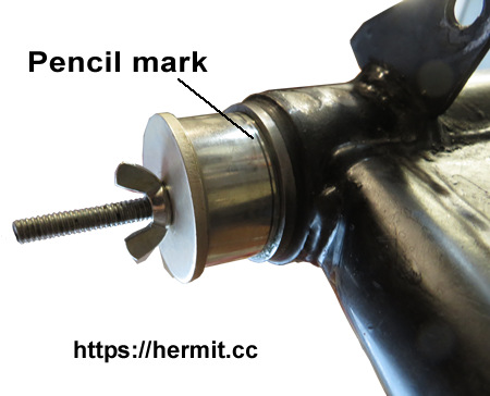
There you have it. I couldn't believe how easy it was to keep the bushes "on-course". The concentric lines took all the guess-work out of starting the bushes on their way perfectly straight and keeping them straight all the way in. Don't be tempted to skimp on penciled circles - I made just three, but another time I would make quite a few more than that just for the peace of mind they bring.
So using the first line as a guide, tap the bush in using a plastic mallet. Once the bushes are off to a good start there are several choices: continue tapping them in with the mallet, or (better) draw them in using a piece of all-thread with a nut and washer at each end; or alternatively, press them in using a twin-screw woodworking bench vise.
Once both bushes are flush with the ends of the swinging arm frame they can be driven in the final 1/8" or so using a drift or a deep socket - a 1-1/8" Harbor Freight deep socket did the trick for me.
(Note: Don't be tempted to put the shocks on before the swinging arm because they'll just be in the way).
In the swinging arm frame, assemble the two "sleeves" (Ref.5, Fig.13), spacer (Ref.6), flanged washers (Ref.7), and new o-rings (Ref.15), packing with grease as you go.
Next, using a wooden dowel to help line things up, insert the long S620 bolt (Ref.8). Loosely thread the nut on and use a grease gun to fill the cavity with grease. This will help keep everything in place while you install the swinging arm frame to the main frame.
Now remove the long bolt and offer the swinging arm frame to the brackets on the main frame. Use a plastic mallet to insert and position the swinging arm frame in the brackets until you can insert the bolt.
Remember that the DS main frame bracket is threaded for the S620 bolt, so insert the bolt from the TS.
Getting the long bolt inserted and lined up to thread into the DS of the main frame can be a fussy job. If fidgeting around and using a plastic mallet to align the swinging arm frame doesn't work, try using an impact screwdriver with a 9/16 BS or 7/8" socket. With a plastic mallet, tap the driver while slowly turning the bolt and it should start threading on.
At this point the swinging arm should be raised and lowered to determine that it lines up with the shock mounts.
Torque the long bolt's nut to 50 lb.ft.. If the swinging arm frame binds too much, back it off very slightly until you obtain the correct friction.
StuartMac tells us that the correct swinging arm friction can be judged as follows:
After tightening the bolt in the frame, install the tab washer (F5944, Ref.9) and S545 nut (Ref.10, Fig.13).
After working on the swing arm and reassembling, instead of folding the tab washer under the nut at the end of the long bolt right away, use a bit of blue Loctite and bend the tab washer after putting a few miles on the bike and retightening.
Resources
Easier to remove with stand folded against frame. Use 3/4" wrench to remove nut (faces out) and then give the bolt a rap to loosen up and start on its way out. Then open the stand and wiggle while pulling on the bolt. Slip the spring off after the bolt is removed.
Nut is up and out or it will be in the way of the spring.
Easiest way to get it on is to put the spring in place on the frame and the sidestand and then pull the sidestand into place.
Resources
Britbike.com "
Centerstand spring"
Britbike.com "Centre stand spring fitting"
Britbike.com "
Bonneville center stand (twisting)"
Hermit.cc "Two Easier Ways to Install a Centerstand Spring"
Over the years Triumph made many changes to the 650 center stands and mounting hardware. Here's a chart that gives the correct part numbers for stands and hardware year-by-year from 1964 to 1985.
Ever arm-wrestle a center stand spring? They're small but mighty! Many swear words have been uttered during center stand spring installations, but happily, there are techniques which can reduce, and possibly even eliminate the amount of brute strength required.
The easiest moment to install a center spring is before putting the stand on the frame and before putting the engine in the frame. Simply flip the frame upside-down and hold it down with your feet, using a towel to protect that new powdercoat of course. Then, hold the loose stand close enough to the frame to slip both ends of the spring into place, and then holding the stand by the legs, pull it into position and slip the bolts in. Easy-peasy! Note this technique relies on pulling instead of pushing.
The job becomes more difficult when the engine and center stand are installed in the frame, but see "Install Center Stand Spring Using String"
Resources
Remove left-hand bracket to make it easier to access the bolt holding the chainguard "C" clamp to the torque stay.
Brackets need to be slack to insert bolt for rear footpegs from behind - best to pre-assemble.
Resources
Workshop Manual (1969 650cc Twins) Section E10: Removing & Replacing the Rear Frame
The 23/34 bolt on the bottom is 5/8" used 1/2" socket.
The 21/34 bolt head is also 5/8", but its 21/34 nut is 11/16", spanner for the former and 1/2"socket for the latter.
Bonnie's frame and tinware
have been powder coated, as well as the following parts:
Not powder coated:
Resources
Hermit.cc Battery Carrier/Oil Tank Mounting (2 photos)
Hermit.cc Battery Carrier (8 photos)
Resources
Workshop Manual (1969 650cc Twins) Section E3: Removing & Replacing the Battery Carrier
This assembly order works well.
It's much easier to install the rubber spigots in the battery holder straps and push them together onto the frame lugs then it is to push the carrier straps over the spigots after they're been installed on the frame lugs.
For more info, see the oil tank main section.
Resources
Workshop Manual (1969 650cc Twins) Section E14: Fitting Replacement Seat Covers
To remove seat, first remove left side panel, then remove bolts for just one seat hinge and slip the other one off.
Install latch: install spring and washer with latch part way inserted, then push in all the way and insert the cotter pin - a pick works well to keep spring and washer in place.
Resources
Britbike.com The Triumph Nacelle", post by Deadstiffcatt.
Of course the late 1960's Triumphs weren't fitted with nacelles, but if you're working on a pre-unit or certain unit models up to 1964 and need some pointers on nacelles, the above post by Deadstiffcatt should be very helpful.
Resources
Workshop Manual (1969 650cc Twins) Section H: Electrical System Table of Contents
Workshop Manual (1969 650cc Twins) Section H-Intro: Electrical System Introduction
Britbike.com
MagnetoMan: "Rewiring a Motorcycle"
Resources
Workshop Manual (1969 650cc Twins) Section H2: Trouble-Shooting the Ignition System
Electrosport.com ""Fault-Finding Flow-Chart for Motorcycle Charging Systems"
If your bike is blowing fuses, this trouble-shooting tip from John Healy will be a great help in tracking down the short: replace the fuse with a 12v light bulb and then begin disconnecting circuits one at a time. When the light goes out you're found the circuit which is shorted. Start looking for faults such as worn insulation or loose bare wires.
Resources
Workshop Manual (1969 650cc Twins) Section H20: Wiring Diagrams
Workshop Manual (1969 650cc Twins) Section HF24: Wiring Diagram (All Export Models)
Workshop Manual (1969 650cc Twins) Section HF25: Wiring Diagram (All Home Models)
Hermit.cc Original Wiring Harness - 2005
Hermit.cc New Repro Wiring Harness - 2006
Hermit.cc Custom Wiring Harness - 2015
Resources
Workshop Manual (1969 650cc Twins) Section H1: Battery Inspection & Maintenance
Fig.23 Battery Carrier/Oil Tank
Hermit.cc Battery Carrier/Oil Tank Mounting (2 photos)
Hermit.cc Battery Carrier (8 photos)
Replacement battery should be a sealed, maintenance-free unit with a minimum 9Ah rating.
For battery carrier dimensions, see Battery Carrier just below.
Possible replacements:
| Brand/Part# | Height | Width | Depth | Notes |
| Koyo YTX-12-BS | 5-1/8" | 5-7/8" | 3-5/16" | 5 stars, but hard to find |
| Motobat AGM MB9U | 5.3" (13.6cm) | 5.2" (13.3cm) | 3" (7.6cm) | 12v/11aH Popular for British bikes |
| PowerStar PM9A-BS AGM | 5-1/2" | 5-1/4" | 3.0" | 12v/9aH |
| PowerStar AGM PS-12-BS | 5-1/8" | 5-7/8" | 3-3/8" | |
| Yasua | 5-1/8" | 5-7/8" | 3-3/8" | (Bonnie - June 2018) |
Resources
Workshop Manual (1969 650cc Twins) Section H12: Fuses
Use 35 amp British fuse (blow current rated), or 15 amp US fuse (continuous current rated).
When I fabricated my own wiring harness I fused both the positive and negative battery terminals.
Fusing both battery leads is effectively like having a spare fuse at all times because the positive battery lead can simply be shorted to ground without a fuse.
Once on a trip in the Green Mountains I turned on the ignition switch while coasting down a steep hill in fourth gear. Bang! A big pop and the negative lead fuse blew. No spare fuses with me - I'd left them on the workbench! I shorted together the positive fuse's carrier leads and put the good fuse in the negative lead.
Battery carrier inside dimensions: H x W x D.
For more info, jump to Battery Carrier section.
Resources
Workshop Manual (1969 650cc Twins) Section H4: Charging System
Workshop Manual (1969 650cc Twins) Section H7: Alternator & Stator Details
John Healy
"Lucas Electrical Stator or Rotor Install Guidance" (PDF)
Britbike.com Stator Installation
TriSpark.com When Lucas 14.5A Three-Phase Stators Fail – What’s Really Going On?
If stator holes won't line up with the stator studs in the crankcase, or the rotor is off-center in the stator, do not be tempted to adjust the alignment by hammering on the studs. Doing so risks cracking the
crankcase. Do any bending with the studs removed and held in a bench vise. (See stator link above).
Resources
Triumph Service Bulletin "Loose rotor center or rotor retaining nut"
Lucas rotors are constructed in two pieces, the center and an outer part which holds the magnets. The center and the outer magnet construct are known to become loose from one another. This defect is not ordinarily repairable - replacement is customary.
A loose condition can be checked for by tightening the rotor in place with the stator removed, gripping the rotor with both hands, and turning the engine in both directions, checking for any slippage.
Note: stator stud nuts torque spec: 30 lb.ft..
When reinstalling the rotor it's very important to ensure sufficient clearance (.008"-.012") between it and the stator - all the way around.
Here's a method often cited at the Britbike Forum:
With engine running and lights on, blip the throttle. If intensity of headlight does not increase with revs there is a problem somewhere in the charging system. This can also be verified by connecting a voltmeter (DC scale) across the battery terminals to see if voltage rises with revs.
The alternator can be checked independently of the rectifier/regulator circuits by connecting either a voltmeter (AC scale) or a 12 volt bulb across the alternator's disconnected leads and kicking the engine over.
Resources
Hermit.cc Original Wiring Harness - 2005
Hermit.cc New Repro Wiring Harness - 2006
Hermit.cc Custom Wiring Harness - 2015
The selenium rectifier and grounding straps have already been disconnected.
(See original and repro photo sets above)
Beneath gas tank.
Tied about an inch to the rear from the "Y" (along with clutch cable)
to upper tube through space in frame forward of the coils. Then tied
again to upper tube just forward of the rear gas tank mount. Passes
over the top of the rear loop into the battery area.
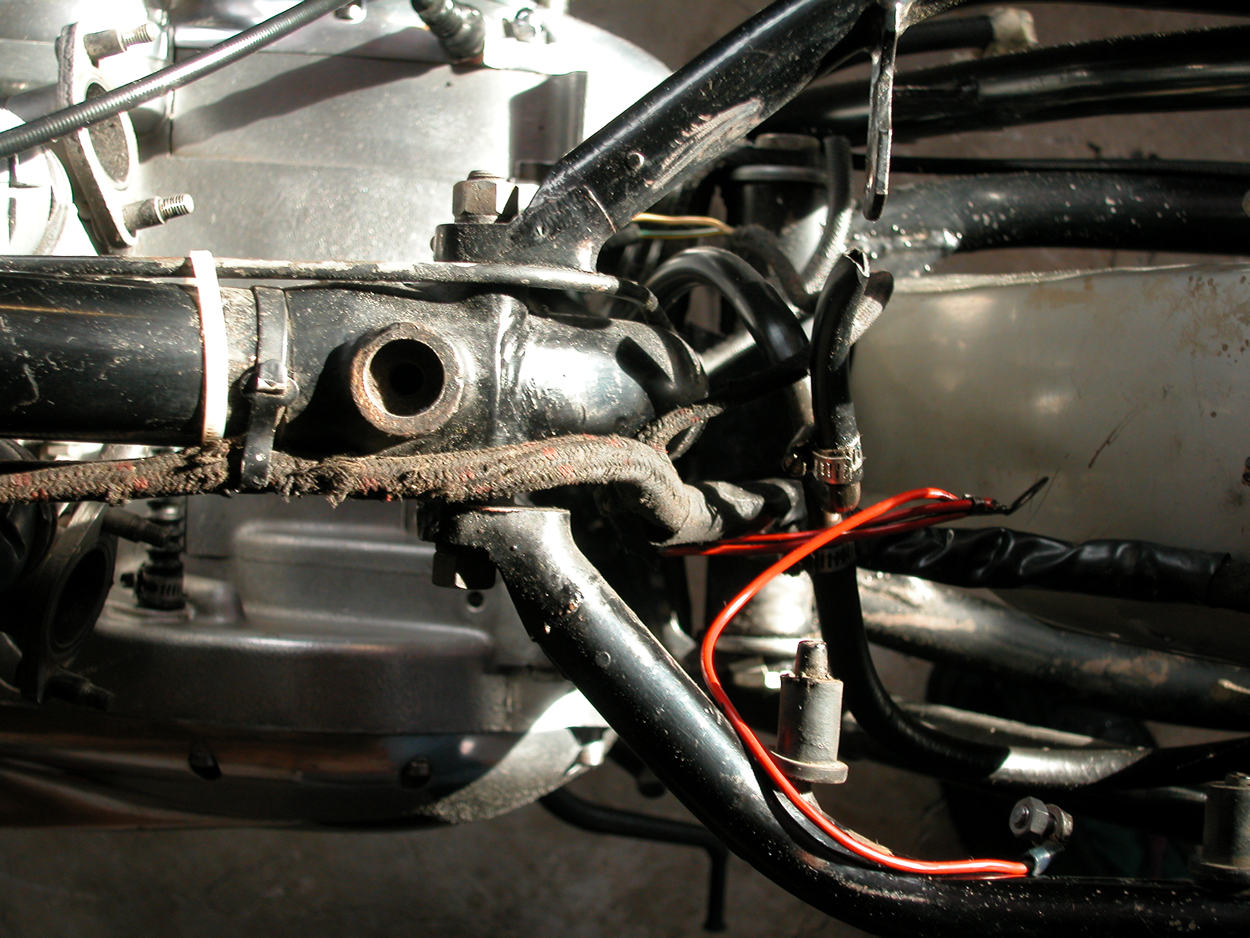 (Photo)
Passes through the stanchions from the rear
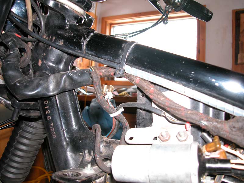 (Photo)
2006: Eliminated horn and integrated dip switch wiring into the Lucas lighting switch in the headlight shell (see wiring diagram above)
2006: Tied just above bottom side cover mounting stud and then falls to follows the frame member before looping to the switch.
Resources
Britbike.com Bullet connectors, crimp or solder? High caliber posts, no hollow points.
Britbike.com
Electrical Work Advice and techniques for soldering.
Bullet connectors are compact, simple, and generally quite reliable. They sometimes get a bad rap for poor connections due to corrosion, but that issue is likely encountered primarily in very humid climates or coastal areas with salty air.
I recently learned that new bullets on the market are sized for metric wire and not the larger Imperial-sized wire found in original British motorcycle wiring harnesses. Accordingly, a modern bullet will not crimp tightly enough to original wiring, even if it's made for the appropriate number of wire strands. Inserting short wire 'shims' to pad out the larger size of the bullets might be a viable work-around.
Some bullets have two crimping points, one for the wires and one for the insulation. The wire crimp makes the electrical connection and the insulation crimp provides strain relief. Bullets available for British bikes today generally have a crimping point only for the wire.
There's some debate over whether it's best to crimp or solder bullets. Crimping provides a good mechanical attachment, and soldering insures good conduction, so to me it's logical to do both. There is, however, one caveat.
Unless done with care, soldering can actually reduce reliability.
When solder flows over individual strands of wire they become effectively solid and rigid. Without the flexibility of strands, solid wire is more prone to vibration stress and eventual breakage. Avoid this by using a very small amount of solder at the tip of the bullet and not allowing it to flow any further than the mechanical crimp. This will preserve the flexibility of the strands leaving the connection and help absorb vibration.
To keep the bullets from falling off the wire while you crimp/solder, strip the wire a wee bit long and splay the protruding ends slightly after inserting the wire into the bullet.
When finished soldering, prevent future corrosion by thoroughly removing traces of flux with a rag and warm water.
If you have the nervous system of a squirrel you might succeed in using a dual-range soldering gun's low setting for soldering bullets, but something like a 35-watt pencil provides greater control over the process. Either way, use a clean, well-tinned soldering tip for best results.
Resources
Workshop Manual (1969 650cc Twins) Section H17: Twintone Horns & Relay
Workshop Manual (1969 650cc Twins) Section H8: Electric Horn
Figure 35 Ign coils, Horn, Rectifier, Zener diode
TriumphRat.net Twin horn relay wiring 1970 T120R
Resources
Workshop Manual (1969 650cc Twins) Section H9: Headlamp
Workshop Manual (1969 650cc Twins) Section H10: Removing/Refitting Headlamp
Custom Headlight Shell Wiring Diagram Wiring Diagram, custom wiring
The headlight reflector unit (99-0686, or LUCAS 516798) is held in the headlight rim (99-0692, or LUCAS 553248) using fixing wires (99-683, or LUCAS 504665).
YouTube.com Classic British Spares: "Installing & Removing Lucas Headlight Wire Clips"
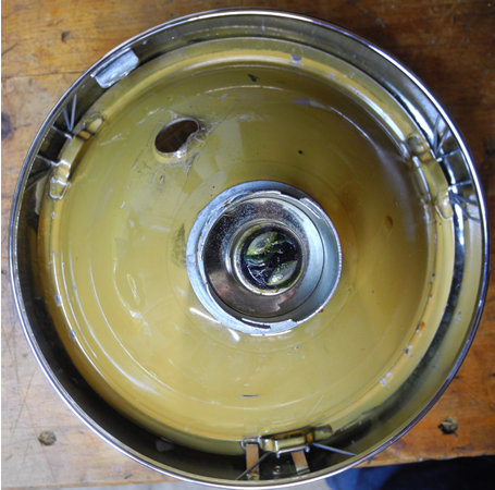
Resources
TriumphRat.net Head/Tail/Brake Light LED Replacements
Britbike.com thread
Brett: "LED headlight bulb test: Now with Pictures!"
Resources
Workshop Manual (1969 650cc Twins) Section H11: Tail & Stoplamp Unit
Workshop Manual (1969 650cc Twins) Section H16: Stop Lamp Switches
Resources
Workshop Manual (1969 650cc Twins) Section H15: Warning Lamps
I've replaced this switch three times on Bonnie. After installing new repro switches I've attempted to recondition the old ones by taking them apart and re-assembling. Never had any success, maybe you're more lucky than me.
The figure below shows the internal connections of the Lucas 35710 (99-0563) light switch in all three positions. See also this
chart-style pin-out for the 35710.
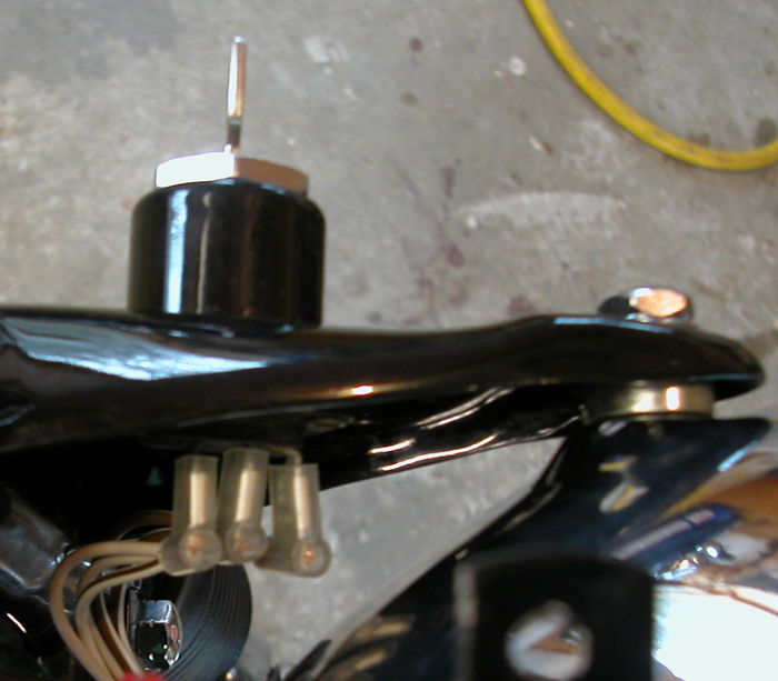
Resources
Workshop Manual (1969 650cc Twins) Section H13: Ignition Switch
Workshop Manual (1969 650cc Twins) Section H14: Ignition Cut-Out Button
Repro editions of the Triumph ignition switch are notoriously prone to failure and the slightest weight of a key fob attached to the key is known to exacerbate the problem - leave your ignition key naked!
An intermittent ignition issue is frequently due to a defective ignition switch. If you're having an ignition problem, one of the first things to do is install a jumper lead from the battery to the coils, thus by-passing the ignition switch.
Connections:
Resources
Workshop Manual (1969 650cc Twins) Section H5: Zener Diode Charge Control & Testing
Workshop Manual (1969 650cc Twins) Section H6: Zener Diode Location
The zener diode is the voltage regulator. When alternator output is too high, it dissipates excess voltage as heat through its heat sink), thus protecting the battery from overcharging, as well as damage to other electrical components.
The selenium rectifier converts the AC alternator output to DC.
Both the selenium rectifier and the zener diode perform well, but if the pricey zener diode fails many will replace both it and the rectifier with a single solid-state device, such as a Podtronics or Tympanium.
Selenium rectifier connections:
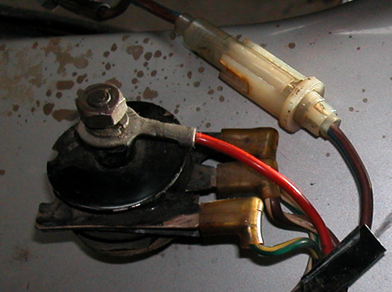
Condensers are only used when running on a points ignition system. They are fitted in parallel with the points and they have two functions to perform.
When the points first start opening, the condenser begins taking on a charge. This draws off the current which might otherwise arc across the small opening points gap. Then, when the points close and the coil's electromagnetic field begins collapsing, the built-up potential across the condenser is discharged through the coil, adding to the energy created in the high tension circuit.
A shorted condenser will create a no-spark condition. An open condenser will cause arcing across the points, pitting them and create misfiring.
To test a condenser with a multimeter, select the thousand-ohm range, place the meter's negative meter against the body of the condenser, and then connect the red meter lead to the positive terminal of the condenser.
Resources
Workshop Manual (1969 650cc Twins) Section H2: Coil Ignition System
On a bike with a points ignition setup it is normal, but not desirable, for one or the other coil to heat up if the ignition switch is left on. This is due to current from the battery energizing the coil through the closed set of points.
If you need to work on the electrical system with the battery connected and the ignition switch in the on position, remove the points cover and slip a piece of paper or plastic between the contacts of the closed points.
EI (electronic ignition) units are programmed to automatically open the coil circuits after a set amount of time if the ignition switch is left on.
Note that the head steadies must be installed before installing the ignition coils.
Note that just because correct resistance readings are obtained for a coil does not mean that the coil is good. It may be arcing internally or its readings may change when the coil becomes warm.
Resistance readings for 6v coils:
Resistance readings for 12v coils:
Left Coil (DS)
Right Coil (TS)
Left coil
Right coil
Resources
Workshop Manual (1969 650cc Twins) Section H19: Capacitor Ignition
Capacitor ignition simply eliminates the battery by substituting a capacitor in its place. The "cap" is of the electrolytic type housed in a small metal can and spring-mounted to isolate it from those good, good, good vibrations. A capacitor does well powering an ignition system with points, although lighting will dim, flicker, and die at idle speed, and at low idle with lights on a bike can easily stall-out in the absence of highly-attentive throttle-blipping.
"Wild Thing" was equipped with a "blue can". Note to self: Photoshop those oil spots!
Caps don't work as well, or at all, with electronic ignition EI systems as they can't constantly provide the minimum required voltage to power such digital devices.
In addition to being stressed by vibration, electrolytic capacitors suffer from high temperatures and their electrolyte paste has a tendency to dry out over time in storage. Newly purchased capacitors should be tested at once using either one of the two simple methods described in the Workshop Manual (link just above).
EI systems such as Pazon, TriSpark, Boyer, Rita, etc. offer some inportant advantages over traditional points systems:
The downside to EI:
To avoid being stranded by a dead EI system many riders resort to carrying a spare with them. A fairly common strategy is to "piggy-back" a spare "black box" with the unit in use to make a switch-over quick and easy should the first unit fail.
A well-adjusted points system will operate with little or even no battery charge. On the other hand, EI systems require a certain base voltage to run the electronics governing timing. Among all the EI systems Pazon is reputed to have the best low-voltage threshold for starting.
When faced with starting a bike with EI and low battery voltage, Peg offers us this logical start-up procedure.
Resources
 Nick, posting on BritBike.com:
"This will tell you if the box or the sensor is the problem."
Resources
VintageBikeMagazine.com "How to Trouble-shoot a Boyer Ignition" Includes good info relating to all EI systems
Resources
Podtronics: Instructions & Diagram
Britbike.com
Podtronics vs Tympanium
Rectifier/Voltage Regulator Installing beneath battery carrier
Both the Podtronics and the Tympanium (as well as Sparx) are solid state devices that replace and perform the functions of the selenium rectifier (rectification of AC alternator output to DC) and the zener diode (voltage regulation).
The Bonnie Ref:
A Hyperlink Junkie's Illustrated Field Guide
to the 1969 Triumph Bonneville
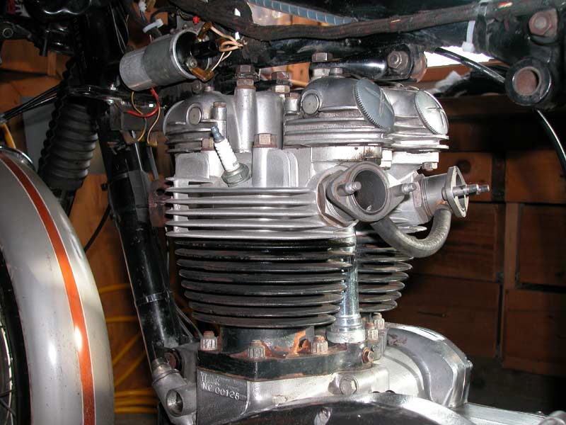
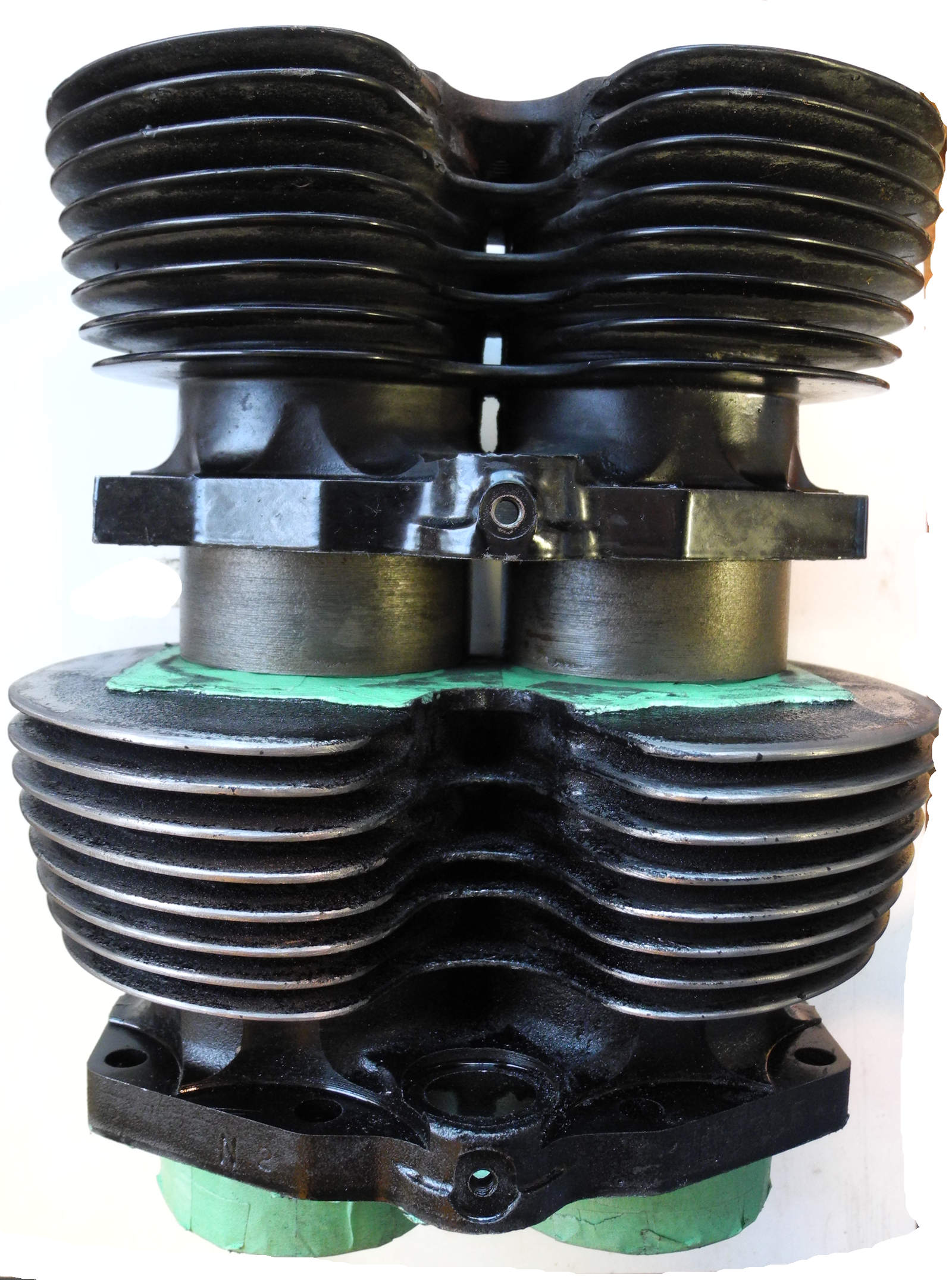