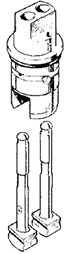

Illustrated Front Fork Leg Assembly
1968-69-70 Triumph 650 and 500
Rebuilding the Triumph 650 Front Fork
Leaking front fork oil seals are annoying, but worn out upper and lower bearings and damaged stanchions are unsafe and your life may depend on them.
Fortunately, restoration of the front fork to like-new condition is possible for nearly any owner willing to acquire a few special tools and make the modest effort required. The step-by-step instructions here are more detailed than the WS-Manual's (link above).
(If you follow the WS-Manual, be aware that it neglects to mention the two pairs of large washers - 97-0431 and 97-1656).
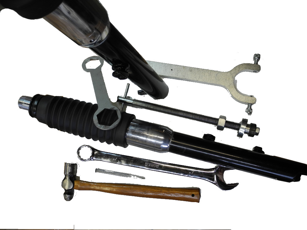
Tools
Work-arounds for the special service tools are possible, such as, for example, a plumber's strap wrench in place of the special wrench for the dust excluder sleeve nut. Highly recommend, however, would be a proper stanchion tube puller.
- Service tool 60-0779 stanchion cap nut wrench
- Service tool 61-6017 dust excluder sleeve nut wrench (or D220F for earlier models)
- Service tool 61-3824 stanchion tube puller
- Quarter-inch drive with a 5/16" socket and extension
- Circlip pliers
- 3/16" pin punch
- Ball peen hammer
- Oil seal drift
- 9/16" combo
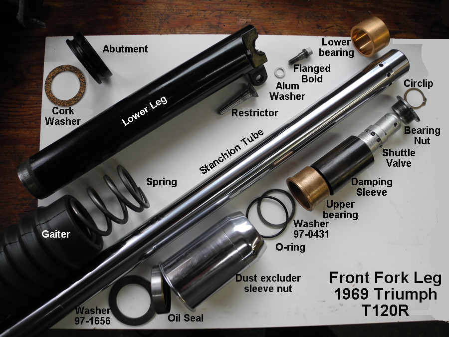
Front Fork Parts
The front fork parts that suffer most from wear are the upper and lower bronze bearings, the stanchions if damaged or high mileage, and of course, the o-rings and oil seals. Springs get weaker over time, and progressive springs are possibly a sensible upgrade.
Part numbers below are for a 1969 T120R unless otherwise noted. Numerous changes were made to the front forks over the years, so consult the Triumph Replacement Parts Catalogue germane to your year and model.
Owners of 1968/69/70 models should read Mike James' "Triumph T120 Fork Changes During 1968 & 1969 Model Years". Mike's concise and superbly illustrated PDF shows how to correctly identify your axels, lower fork legs, and stanchions, as well as how to avoid the pitfalls of incorrect and undocumented part numbers during these years. A must-read!
Shown below are the front fork parts of a 1969 Triumph 650 T120R motorcycle. The "exploded-view" arrangement of the parts suggests their assembly.
Step-by-Step Fork Leg Assembly
(For Disassembly, see "Dismantling Front Fork Legs")
- Fit lower bearing 97-0443 onto bottom end of a stanchion (97-2092).
The lower bearing should be a snug fit - if necessary tap it on using a mallet and a piece of hardwood, checking progress to insure the bearing is going on straight.

The
pencil line tip for starting swinging arm bushes also works really well for installing the upper and lower fork bearings!
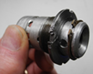
- Pre-assemble shuttle valve 97-2154 into bearing retaining nut 97-2091 and retain it with circlip 97-2127.
- Thread the assembly right into the bottom of a stanchion tube (97-2092).
A "C"-wrench would be ideal for tightening the notched retaining nut, but alternatively one could use a pair of slip-joint pliers with a rag to protect the nut.
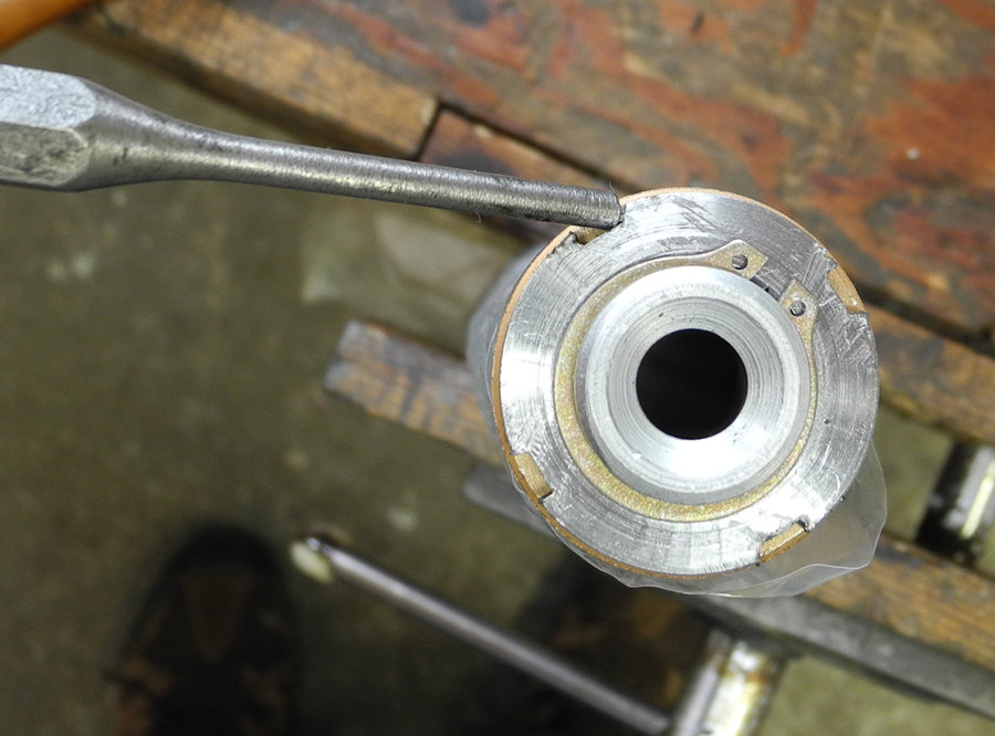
Another possibility is to use a 3/16" pin punch and tap lightly all-around on the nut's notches with a brass nacho or ball peen hammer.
- Insert restrictor 97-2090 into one of the lower legs (97-2294, left; 97-2295, right) with the hex head against the bottom of the lower leg and the restrictor's pointed end facing up.
I use a speed wrench, an extension, and a 5/8" deep socket to insert and hold the restrictor in place.
It's ok if the restrictor's head is recessed a bit in the deep well socket, the flanged bolt will reach it and you'll be able to fiddle it on.
- Lower an inverted lower leg over the socket and restrictor all the way down until it comes to rest against the socket inside.
- Insert flanged bolt 97-2126 with aluminum washer 97-1062 into the recess at the bottom of the lower leg.
The recess diameter is not generous, tightening the flanged bolts requires a quarter-inch drive with an extension and a somewhat thinnish 5/16" socket.
Thread the bolt into the restrictor inside the lower leg - be patient, jiggle things a little, try again, there! That wasn't so bad!
- Flip the lower leg around in the vise so it is right side up and insert the stanchion and bottom bush assembly into the lower leg.
- Slide the plastic damper sleeve 97-1896 down the stanchion with the THICK END DOWN - be sure now, thin up, thick down.
- Slide upper bearing 97-0441 down the stanchion
- Slide the skinny plain washer 97-0431 down the stanchion.
- Install oil seals in the dust excluder sleeve nuts (97-3633) -
Smear a little grease inside the dust excluder sleeve where the oil seal goes and also around the outside of the oil seal.
Place a dust excluder sleeve nut right side up on the workbench and - SPRING SIDE DOWN - lower an oil seal into it until the seal rests against the dust excluder sleeve's shoulder.
Drop a 97-1656 thick plain washer on top of the oil seal and then use a suitable drift to seat the oil seal all the way.
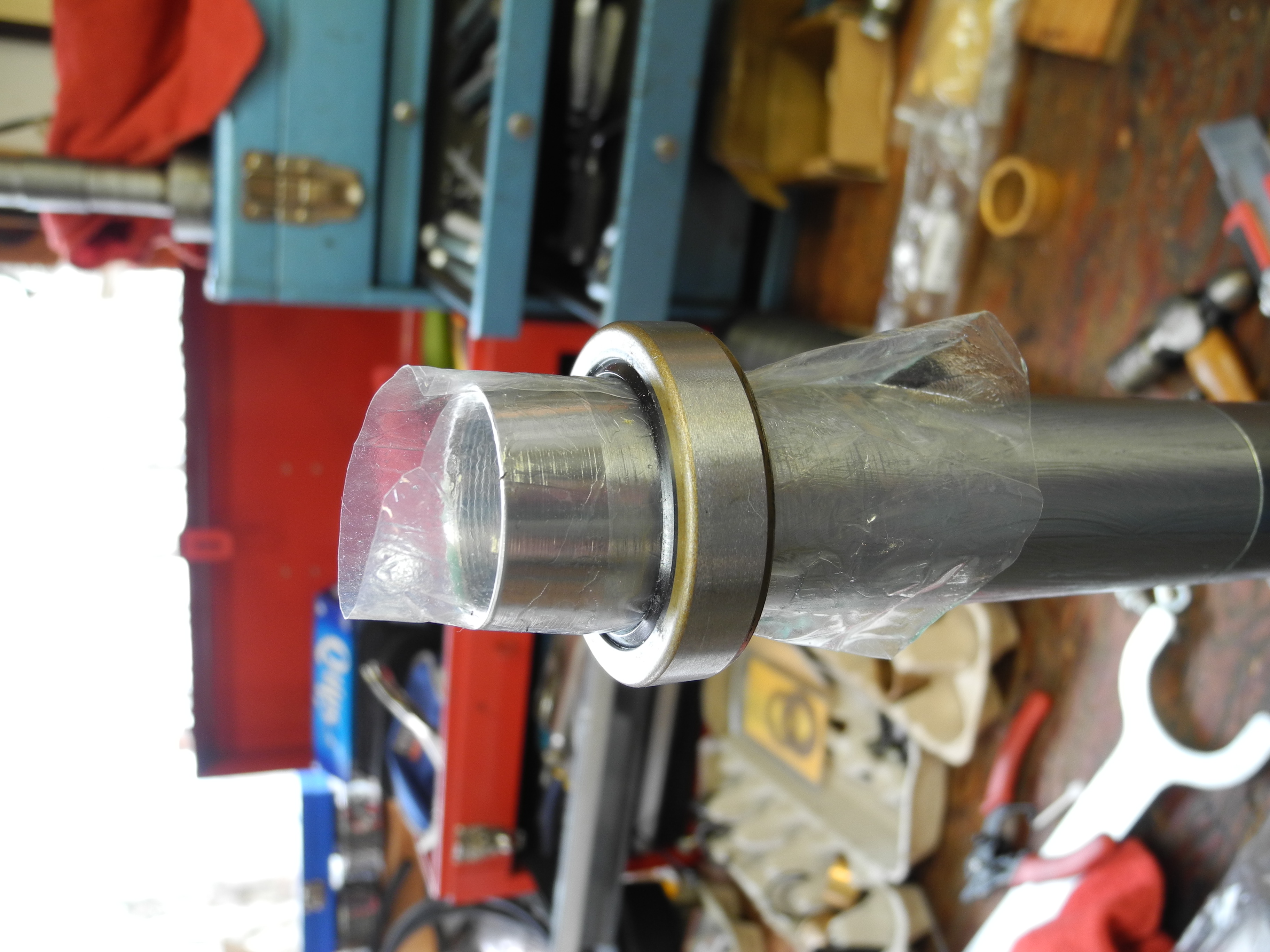
- Next, with the lower leg gently held in a vise, slide a dust excluder sleeve nut with its oil seal and o-ring down the lightly greased stanchion.
If used stanchions are rusty, or have witness marks from yokes or the previous efforts of other craftsmen, first clean and smooth them with fine emery paper before greasing.
If there's still a chance of surface blemishes nicking the oil seal's lip, wrap the stanchion with plastic wrap as far down as possible and grease it - or, cut the end off a thin plastic bag and use it to sled the seal over the rough spots.
- Screw the dust excluder sleeve nut onto the lower leg. I clean these threads up first on a wire wheel with a couple layers of masking tape to protect the paint.
I used Teflon tape the first time I assembled fork legs and had no leaks. I neglected to use anything the second time and there were no leaks, but occasionally a very slight weep on the DS. Now, on this third assembly, I'm trying out using anti-seize paste.
(Note: Only one year passed before I disassembled the fork legs again (had to have tapered ends of new stanchion tubes machined to fit properly in the upper triple-tree), but the anti-seize paste made removing the dust excluder sleeve nut very easy and there had been no oil leaks so I will use it again.)
- Tighten the sleeve nut with service tool 61-6017 (D220F for earlier models).
The service tool is a good investment but it is quite expensive. There are alternatives, including
rubber-coated strap plumbing wrenches, hose clamps, and home-made tools such as
this, and this.
- Replace big plain washer 97-1656.
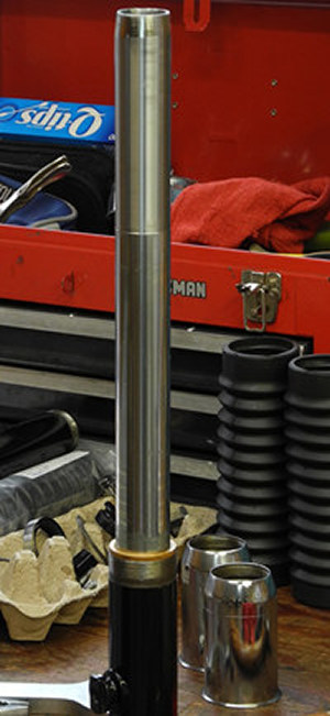
- Slip a fork gaiter (97-3635) over a spring (97-1892) and lower them together over the stanchion.
Observe indications of gaiter orientation - fitment on top, pin hole down.
General consensus for progressive type springs is tighter-wound coils up.
- Fit abutment 97-1657 over the stanchion followed by cork washer 82-4047 on top.
- Fit fork covers 97-2161 (left) and 97-2162 (right) between upper yoke 97-3667 and lower yoke 97-2288.
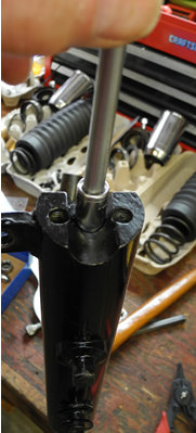
- Insert a completed stanchion assembly as far as possible through the lower yoke, giving attention to it's correct side (TS for lower leg with brake plate lug).
To help ease the stanchion through the lower yoke, you may need to open the yoke very slightly using a hardwood wedge.
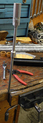
- Insert service tool 61-3824 through the top yoke and screw its threaded plug into the top of the stanchion - below, left.
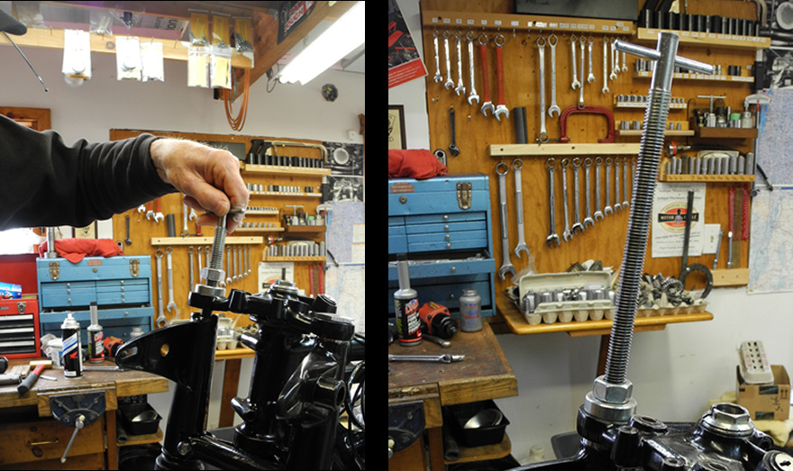
This tool is also sometimes referred to as Z161 (CEI threads) or Z170 (UNF). Commonly sold under the number 61-3824 as a kit which includes interchangeable heads that accommodate different sizes of stanchions with different threads.
- Tighten the top nut of the service tool until the stanchion is fully fitted into the upper yoke - above, right.
- Insert a lower pinch bolt 97-2290 through the dust cover and tighten sufficiently to hold the stanchion in place.
- Remove the service tool and thread a cap nut into the stanchion.
- Repeat above steps for the second stanchion.
- Remove the cap nuts and pour 200cc (20 oz) of fork oil into both stanchions.
- Replace both cap nuts.
- Loosen the lower pinch bolts.
- Tighten the cap nuts (80 lbs/foot).
- Adjust steering head races.
- Align the front fork.
- Tighten upper pinch bolt (15 lb/foot) and middle pinch bolts (25 lb/foot).
Go for a ride and enjoy the wonderful feel of your like-new front forks!
 Workshop Manual (1969 650cc Twins) Section G6: Reassembling and Refitting the Telescopic Fork Unit