
Over 400 photos were processed in order to create this unique photo animation and the accompaning sets of five still photos that accompany it.
The resulting animated GIF completely illustrates the inner workings of the Triumph gear cluster, complete with shifting forks and camplate, as it shifts up and down through all four gears and neutral (looping, approximate four-second delay).
You can take more time to analyze each configuration of the gears by examining the series of still photos below the animation.
Depending upon the bandwidth of your Internet connection and whether or not you are a speed reader, the animation (1.75MB animated GIF) may be already running, or still downloading. In case of the latter, please be patient, it will start soon.
(Click Animation for Enlargement
Note, the animation must reload when you do so)
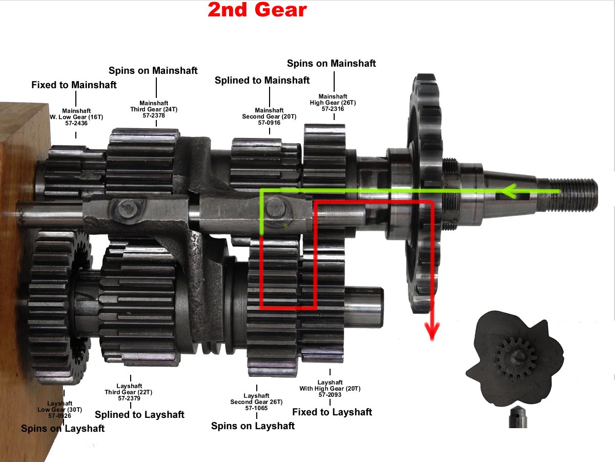
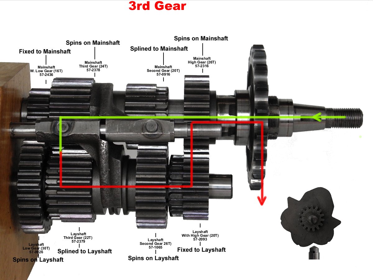
In addition to freezing the action, the still photos diagram the path of power from input (the clutch end of the mainshaft) all the way to output (the gearbox sprocket) for all four gears.
Choose between two views:
Both views enlarge the photos and open in a new tab. If you open all the gears (either view) in their natural order (1st, neutral, 2nd, 3rd, 4th) you can manually flip back and forth to better observe and understand all the action.
(Tip: For convenience, Right-click links, then Click "Open Link in New Tab")
To open the illustrations serially in only one tab, Left-click on the images themselves.
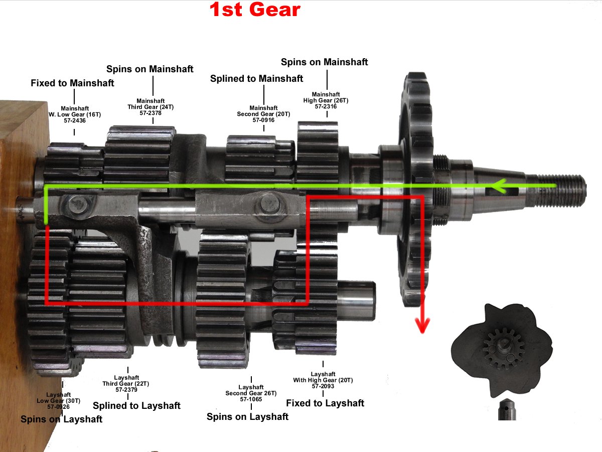
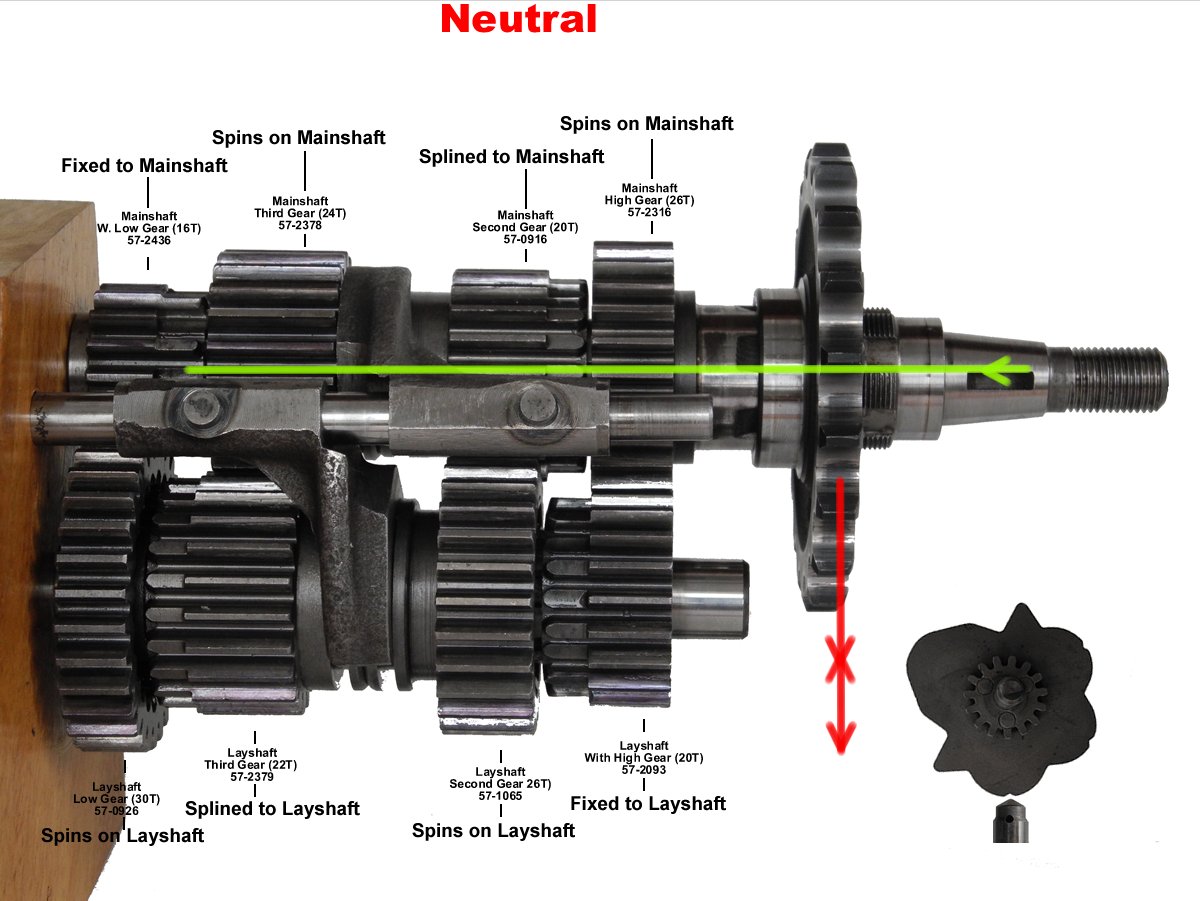

The green and red dots on the camplate (seen in rear view only) represent the positions of the gear selector fork pins in the camplate's groove as they slide the selector forks back and forth, engaging and disengaging gears.
Here in the Front View, the layshaft gear selector fork is shown to the left, while the mainshaft selector fork appears at the right.
The pear-shape of the camplate's groove around it's center is what controls timing and direction of movement of the gear selector forks.
Even as the camplate turns, no movement is made by a peg or its selector fork while the peg glides within the constant radius of the circular part of the camplate's groove. While a peg is in this position, its selector fork is disengaging the dogs of both sliding gears on it's respective shaft.
A pin must be engaged by the elongated portion of the camplate before it begins moving and slides its gear selector fork.
Note that dogs only ever engage on one shaft at a time. While one gear selector fork engages either one of the two sets of dogs on its shaft, the other selector fork disengages both dog sets on its shaft. So while one peg is being moved by the camplate, the other peg is captured, unmoving, within the circular part of the camplate groove.