

Depending upon whether the machine is an earlier or later model, the three positions of this switch are either:
But seriously, the following table shows the inter-connections for the terminals used by the wiring harness (i.e. 4,6,7, and 8) in all three switch positions. Open connections are represented by "0", and closed connections are represented by "1".
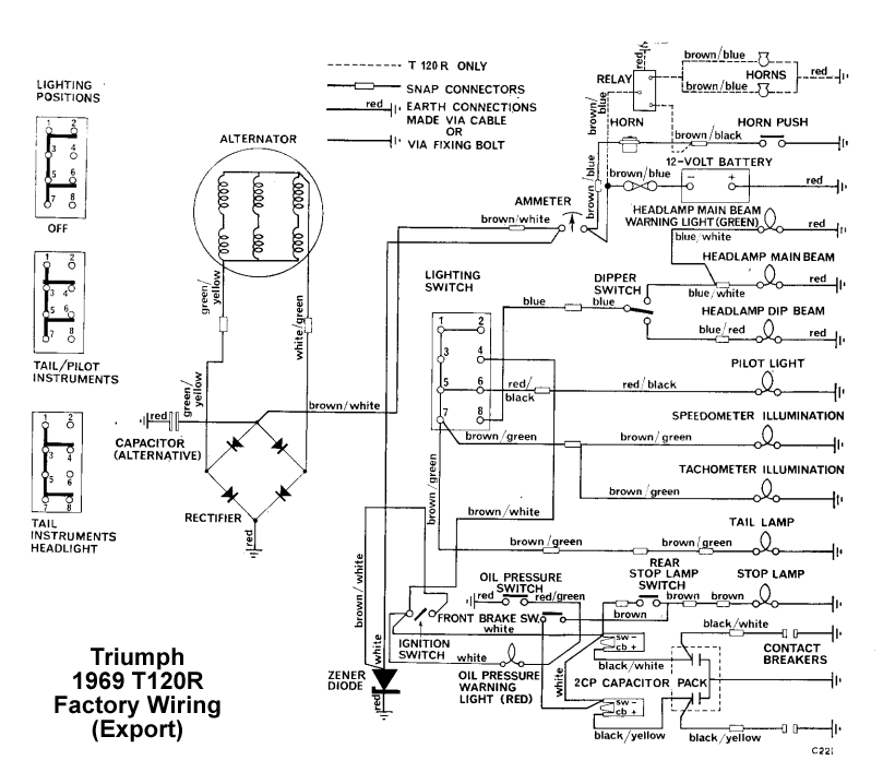
A schematic diagram of the 1969 T120R electrical system showing the switch connections follows the table.

|
From Terminal # |
To Terminal # |
Switch Position 1 |
Switch Position 2 |
Switch Position 3 |
| 1 | 4 | 0 | 1 | 1 |
| 1 | 6 | 1 | 1 | 0 |
| 1 | 7 | 1 | 1 | 1 |
| 1 | 8 | 0 | 0 | 1 |
| 4 | 6 | 0 | 1 | 0 |
| 4 | 7 | 0 | 1 | 1 |
| 4 | 8 | 0 | 0 | 1 |
| 6 | 7 | 1 | 1 | 0 |
| 6 | 8 | 0 | 0 | 0 |
| 7 | 8 | 0 | 0 | 1 |
| 3 | Normally Closed | - | - | - |
| 5 | Normally Closed | - | - | - |

Schematic diagram of original factory Triumph 650 T12oR electrical system